<i>Welcome to this exciting series of everyday electronics where I get you very close to electronics components, their use and how to recognize them.</i>
555 timer is a very basic electronic component found in many electronic circuits and probably the world's most popular integrated circuit. It has been in use in a standard electronic circuit since the early 1970s. 555 timer has a wide range of applications including regulator circuits like the stabilizers in the home, frequency regulators, temperature measuring devices, oscillators, etc.
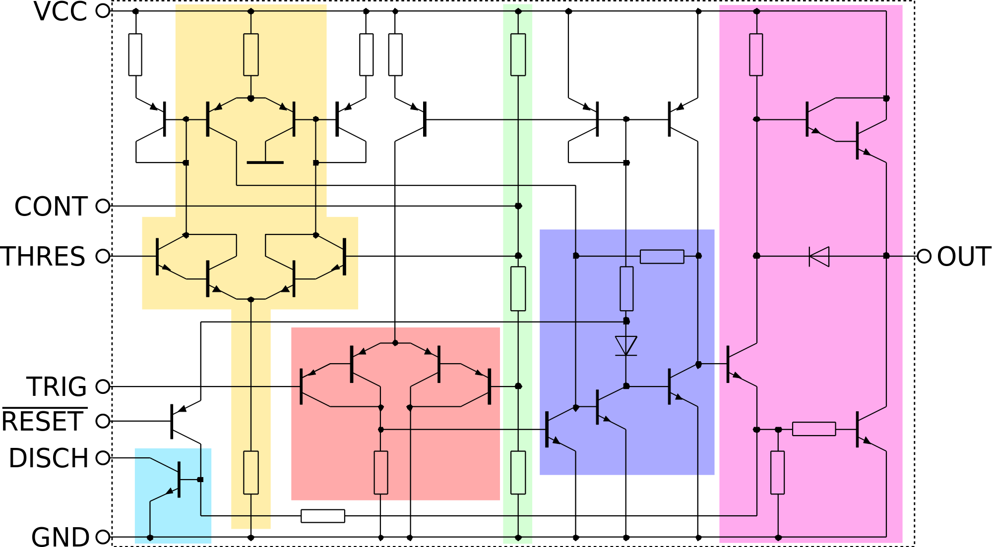
[<i>internal schematics of the 555 timer</i>. credit: <a href="https://commons.wikimedia.org/wiki/File:NE555_Internal_Circuit.svg">wikimedia</a>]
Oscillator circuits are very important in the sense that they can generate periodic electric signals in the form of a square or pure sine waveforms. A very practical application of oscillators is in generating pulse width modulated electrical signals. Pulse width modulated electrical signals can be used in complex control circuits for regulating the speeds of electrical motors, dim the brightness of LEDs and many other circuit delays. I started today's everyday electronics by stating a few applications of 555 timers to show that it is a component you need to know and get to use!
The 555 timer is a linear IC which means that it is an analog <a href="https://en.wikipedia.org/wiki/Solid-state_electronics">solid state device</a> which has infinite operating modes. From the schematics above, the 555 timer has a transistor count of 25 transistors organized in <i>current mirror</i> and <i>differential pair</i> arrangements, 16 resistors and 2 diodes. The 555 in the name comes from the 3 5 kilo ohms resistors (colored in light green in the image above) arranged in voltage divider mode creating voltage references of 2/3 and 1/3 of the input voltage.
<h6>The current Mirror</h6>
<div class="pull-left"><center><img src="https://steemitimages.com/0x0/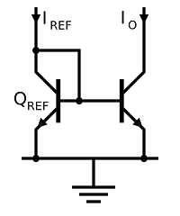)" /><br /><em><a href="https://commons.wikimedia.org/wiki/File:Basic_BJT_Current_Mirror.svg" rel="noopener">[credit: wikimedia]</a></em></center></div> The arrangement of transistors in the image shown on the left is very dominant in the schematic of the 555 timer shown above. Implementing resistors in intergrated circuits are always difficult because obtaining exact or close to exact value is usually not possible hence we see resistance in ICs varying by up to 50% among chips with the same components.
<br>
This makes IC designers implement resistors in ratios and not specific values. The current mirror solves this problem to a great extent since the current mirror can conveniently take the place of resistors in chips and also gives a more identical current when compared to the current output of resistors. The current mirror consists of two identical transistors with a known input reference current <i><b>Iref</b></i> passing through the emitter of the transistor on the left, this same current is mirrored to the left transistor since two transistors possess the same emitter and base voltage.
<h6>The differential Pair</h6>
<div class="pull-right"><center><img src="https://steemitimages.com/0x0/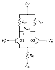)" /><br /><em>[<a href="https://commons.wikimedia.org/wiki/File:Differential_amplifier_long-tailed_pair.svg" rel="noopener">credit: wikimedia</a>]</em></center></div>The differential pair is also very visible in the schematic diagram of the 555 timer circuit shown above and is a very important part of any analog IC. The differential pair functions to compare two input voltages just like the traditional <a href="https://en.wikipedia.org/wiki/Comparator">comparators</a> or to subtract a certain amount of voltage from an input voltage just like the normal <a href="https://en.wikipedia.org/wiki/Operational_amplifier">operational amplifiers</a>.
<br>
Two of such circuit exists in the 555 timer at the <b>threshold</b> and at the <b>trigger</b>. A current sink exists between the Vee and the Re providing a fixed amount of current which is then split at the collector end of both transistors. If Vin+ and Vin- are equal, the input current is divided into two equal parts and emerges at the collector of both transistors but if the input voltage of one of the transistors (either Vin+ or Vin-) becomes the transistor with more input voltage will <a href="https://en.wikipedia.org/wiki/Bipolar_transistor_biasing">bias</a> its base thereby allowing more current to flow leaving the transistor with lesser voltage the lesser amount of current.
In the 555 timer, two comparators are implemented at the Threshold (painted peach) and at the Trigger(painted coral) (shown in the schematic above). The comparator at the threshold exists close to the input voltage, Vcc while the comparator at trigger exists close to the Ground (GND).
<h6>Pin configurations</h6>
<hr>
<div class="pull-right"><center><img src="https://steemitimages.com/0x0/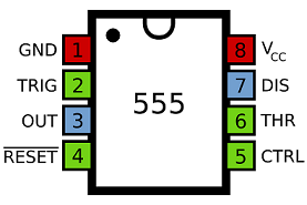)" /><br /><em>[<a href="https://commons.wikimedia.org/wiki/File:555_Pinout.svg" rel="noopener">credit: wikimedia</a>]</em></center></div> The packaging of the 555 timer IC is usually in two forms, the 8 pin dual inline package, DIP (shown right) and the 8 pin metal can. The pin numbering I will explain subsequently will follow the arrangment of the DIP.
<h6>Pin 1 (Ground)</h6>
The ground is also known as the common and represents the point in the device where the potential is most negative. This is taken to be the reference point in the device since all the voltages in the devices are measured wrt this terminal.
<h6>Pin 2 (Trigger)</h6>
This terminal is connected to the inverting end of the comparator discussed in the differential pair above. This pin is very important in the monostable mode (discussed below) as it makes the flip flop circuit to go high or to move from set mode to reset mode. The flip-flop helps to keep the electric signal in either high (On) or Low (Off) until the reset is sent across through the reset pin (pin 4).
<h6>Pin 3 (Output)</h6>
The output generated by the timer is sent to this pin. A load can be connected to the output pin by either making a connection between this pin and ground (pin 1) or making a connection between this pin and the voltage input pin (pin 8). When the load is connected between pin 1 and pin 3, the load is said to be in <i>normally on-load</i> but when a load is connected between pin 8 and pin 3, the load is said to be in <i>normally off-load</i>.
<h6>Pin 4 (Reset)</h6>
This pin is used to reset the flip-flop state. In order to do this, a negative signal is sent to this pin, hence to prevent the timer from resetting itself, this pin is advised to be always connected to the positive voltage source (Vcc). A current of 0.1milliAmpere and voltage of 0.7volt regarded as the reset threshold voltage level is required to reset this device.
<h6>Pin 5 (Voltage Control)</h6>
As stated initially, three resistors form a voltage divider which divides the input voltage into 1/3 and 2/3 reference voltage points. Connection to this pin gives access to the 2/3 input voltage level which is a connection to the upper part of the comparator. When we apply a voltage to this pin, we can control the resulting pulse without relying on the resistor-capacitor circuit (RC circuit) in the timer.
<h6>Pin 6 (Threshold)</h6>
Just like pin 5 gives us access to the upper part of the voltage comparator, this pin also gives us access to the upper part of the comparator and helps us to reset the flip-flop to the low state. Resetting the flip-flop through this pin involves from a low voltage level up to a voltage level of two-thirds of the input voltage. Voltage operations of this pin are very sensitive and allow the resulting waveforms to change slowly.
<h6>Pin 7 (Discharge)</h6>
The name of this terminal comes as a result of the fact that when transistors saturates, it causes capacitors to discharge using the transistors. The internal connection of this pin consists of a capacitor connected between the pin and the collector of the transistor (painted sky-blue in the schematic) at the discharge end. When the transistor is not saturated (in cut-off region), the capacitor is allowed to charge and the rate at which this capacitor charges can be controlled using external RC circuit.
<h6>Pin 8 (Supply voltage)</h6>
This is also known as the Vcc and it’s the point of connection of the positive voltage supply usually between the range of 4.5v to 18v. This shows that the 555 timer has a wide range of input voltage cause voltages within this range produces the same timing period.
<h6>Operating modes</h6>
<hr>
The 555 timer is found basically in two operating modes. The monostable and the astable mode. though many argue it has a third operating mode which is the combination of the above-mentioned modes. Hence, understanding the basic two operating modes will give you access to combining the two modes to make the "third mode".
<h6>The Astable mode</h6>
<div class="pull-left"><center><img src="https://steemitimages.com/0x0/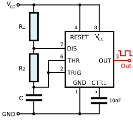)" /><br /><em>[<a href="https://commons.wikimedia.org/wiki/File:555_Astable_Diagram.svg" rel="noopener">credit: wikimedia</a>]</em></center></div> In this mode, the 555 timer produces a continuous pulses with frequency of about 2 MHZ. To achieve this the output pin is constantly switching between high and low state throwing up pure square waves. At this mode, the 555 timer acts only as an oscillator.
<br>
The frequency at which the timer switches between two voltage levels and the total amount of time the voltage level is on the On state (duty cycle) are all dependent of the value of the resistor-capacitor circuit components arranged in the image shown to the left.
To adjust the amount of <b>On</b> or <b>Off</b> states of the oscillator (the 555 timer now an oscillator), the formula below can be used:
>Ton = C * 0.69 * (Rt)
Tof = C * 0.69 * R2
Where Rt=R1 + R2, C = capacitance of the capacitor connected between R2 and GND
<h6>Monostable Mode</h6>
<div class="pull-right"><center><img src="https://steemitimages.com/0x0/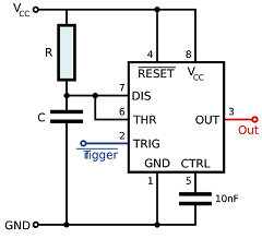)" /><br /><em>[<a href="https://commons.wikimedia.org/wiki/File:555_Monostable.svg" rel="noopener">credit: wikimedia</a>]</em></center></div>In the astable mode, two resistors forms a voltage divider at the discharge pin with the output of one resistor connected to both the threshold and the trigger. The same cannot be said for the monostable mode as the simplicity of the control circuit is very obvious, just a capacitor and a resistor controls the output pulse which is just a single pulse of current occurring for a defined period of time.
<br>
This mode also has a wide range of application for instance we can connect an LED to the output and have the LED toggled to ON state for about 10 seconds after a push of a button and again toggled back to normal Off state.
The amount of time this bulb stays on the high state can be calculated using
>Ton = 1.1 * C * R
Where C and R are the external capacitor and resistor respectively.
From the equation above, it can be seen that the amount of "on" state of the output pulse can be increased by increasing the size of both the external resistor and capacitor since their relationship with time is linear.
<h6>Summary</h6>
The 555 timer is one of the most widely ICs in diy electronic circuits because it is relatively cheap and easy to use. It has very wide input voltage tolerance and can offer perfect delays in circuits. It can also be used in voltage conversions and regulations. It basically has two operating modes which can be leveraged in building a very robust electronic circuits.
The 555 timer discussed here has many variants and advanced versions like the CMOS Motorola MC1455, the 558 timer which a combination of four 555 timer available in 8 pin DIP IC packaging. I hope you found this piece very informative and I'd like to thank you for your time.
Feel free to use the comment section to ask me question if you encounter any problem making implementation using this very IC, the standard datasheet for the 555 timer can be found <a href="http://www.ti.com/lit/ds/symlink/lm555.pdf">here</a>.
<hr>
<h3>Reference</h3>
1. <a href="http://www.righto.com/2016/02/555-timer-teardown-inside-worlds-most.html
">555 Timer teardown -Righto</a>
2. <a href="https://en.wikipedia.org/wiki/555_timer_IC">555 timer IC -wikipedia</a>
3. <a href="http://www.circuitbasics.com/555-timer-basics-monostable-mode/">555 timer monostable mode -circuit basics</a>
4. <a href="http://www.circuitbasics.com/555-timer-basics-astable-mode/">555 timer astable mode -circuit basics</a>
5. <a href="http://www.fluke.com/fluke/caen/community/fluke-news-plus/articlecategories/electronics-news/555-timer">Long live the 555 timer -fluke</a>
<hr/>
<hr/>
<sup>
If you write STEM (Science, Technology, Engineering, and Mathematics) related posts, consider joining #steemSTEM on steemit chat or discord here. If you are from Nigeria, you may want to include the #stemng tag in your post. You can visit this blog by @stemng for more details. You can also check this blog post by @steemstem here and this guidelines here for help on how to be a member of @steemstem.</sup>
<center></center>
<img src="https://steemitimages.com/0x0/https://steemitimages.com/DQmRhDtjokAZnGKi4QwheqksKTFo6m4fsjMYsNNrsitC1xk/DQmRhDtjokAZnGKi4QwheqksKTFo6m4fsjMYsNNrsitC1xk.gif" alt="DQmRhDtjokAZnGKi4QwheqksKTFo6m4fsjMYsNNrsitC1xk.gif" />