<div class= "text-justify">
Greetings public scientist of steemit for this post I want to show you an interesting topic related to the discovery of the [_**electron**_](http://whatis.techtarget.com/definition/electron) and its relation _**load-mass**_ made at the end of the 19th century.
Although already by the year 1897 work was experimentally and theoretically with electricity to such an extent that Maxwell's equations were known, the precise existence of the electron was not known as a subatomic particle constituent of matter. The investigations of [Johann Wilhelm Hittorf](https://www.britannica.com/biography/Johann-Wilhelm-Hittorf), [Eugen Goldstein](https://www.britannica.com/biography/Eugen-Goldstein) y [Willians Crookes](https://www.britannica.com/biography/William-Crookes) they opened the way and established the basis for [Josep John Thomson](https://www.nobelprize.org/nobel_prizes/physics/laureates/1906/thomson-bio.html) (1856-1940) by means of a series of experiments with the use of [_**cathode ray**_ ](https://en.wikipedia.org/wiki/Cathode_ray) tubes, the existence of the electron called by him, at that time as "corpuscles". A montage similar to the experiment developed by Thomson is illustrated in Figure 1, which consists of a vacuum glass vessel and inside an electron gun formed by two electrodes a cathode (negative) and an anode (positive), so that when the cathode is heated, electrons are released from its surface and accelerated by an external voltage (**V**) that flows towards the anode, generating an electron beam, said flow is subjected to an electric and magnetic field placed perpendicularly to each other and to the direction of the beam that hits the back of the container, which is covered by a luminescent material and allows visibility of the beam[[1](https://www.nyu.edu/classes/tuckerman/adv.chem/lectures/lecture_3/node1.html)].
- - -
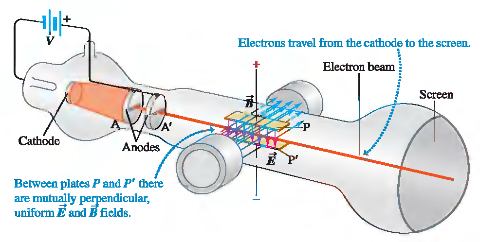
<center> [_**Montage of the Thomson experiment**_](http://www.physics.upenn.edu/~thomsone/phys151/Figure27_21.jpg)</center>
- - -
Adjusting the intensity of magnetic and electric fields that alter the direction of the beam, Thomson was able to determine the speed of electrons, to then obtain the ratio _**load-mass**_ by the sole influence of the electric field, with a magnitude of value:
<center>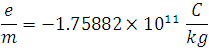<div class= "pull-right"> **([1](https://physics.nist.gov/cgi-bin/cuu/Value?esme))**</div> </center>
So as you can see **(1)** is not more than the ratio between the charge of the electron and its mass, whose only quantity was the one Thomson found independent of any variable used in the experiment as the cathode material or the residual gas in the tube, concluding that the particles that make up the beam (electrons) are a common element of all matter, such result made him worthy of the discovery of the first subatomic particle, today well-known as the _**electro**_
Now the method described below uses the same principle, unlike in this process the magnetic field will be generated by a pair of [_**Helmholtz coils**_](https://en.wikipedia.org/wiki/Helmholtz_coil) shown in Figure 1, and without the presence of an electric field.
<center>https://upload.wikimedia.org/wikipedia/commons/thumb/8/8d/Helmholtz_coils.png/255px-Helmholtz_coils.png</center>
<center> [_**Figura 1**_](https://upload.wikimedia.org/wikipedia/commons/thumb/8/8d/Helmholtz_coils.png/255px-Helmholtz_coils.png)</center>
The theoretical foundation that sustains this study is shown by the following considerations:
### <center>**Theoretical framework and assembly** </center>
The [_**Lorentz Force**_](https://www.britannica.com/science/Lorentz-force) equation expresses that a charge  that moves with a velocity  in the presence of a magnetic field , experiences a force  perpendicular to the plane that contains the velocity and field vector, this expression is given by:
<center>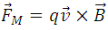<div class= "pull-right"> **(2)**</div></center>
Now, since in our experiment  and  are perpendicular, and taking e as the load must be fulfilled by the definition of the [cross product](https://www.mathsisfun.com/algebra/vectors-cross-product.html) the following:
<center><div class= "pull-right"> **(3)**</div></center>
The previous expression is the magnitude of the _**magnetic force**_, which causes the electrons to describe a circular movement, in whose trajectory the _**centripetal force**_ of magnitude is also present:
<center><div class= "pull-right"> **(4)**</div></center>
and illustrated in figure 2:
<center></center>
<center>_**Figura 2 :**_ Circular motion given to a magnetic field perpendicular to the path of the electron</center>
Where  is the mass of the electron,  the speed and  the radius of the circular motion that describes. Because both forces are present in the same movement then we can equal **(2)** and **(3)** in this way:
<center>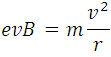</center>
Looking for the relationship of the constant we have:
<center><div class= "pull-right"> **(5)**</div></center>
From (5) we see that  we are left as the ratio of  between the product of  by , but since the electrons gain kinetic energy due to the applied potential we can make the following consideration:
<center><div class= "pull-right"> **(6)**</div></center>
**(6)** expresses that necessarily the potential energy supplied through **V** is equal to the kinetic energy generated, neglecting other factors such as the loss of energy through heat by the collisions between the electrons and the gas molecules contained in the container, but since said substance is at very low pressure, such an approach is considered appropriate within this modeling.
Clearing the of **(6)** we get:
<center><div class= "pull-right"> **(7)**</div></center>
The magnetic field in the center of the Helmholtz coils is given by:
<center><div class= "pull-right"> **([8](https://www.didaktik.physik.uni-muenchen.de/elektronenbahnen/en/b-feld/B-Feld/Helmholtzspulenpaar.php))**</div></center>
Now substituting **(7)** y **(8)** in **(5)**, and doing the algebraic steps we have:
<center><div class= "pull-right"> **(9)**</div></center>
The previous expression is the relationship  used to obtain the value of the constant with the **Helmholtz coils**, It can be observed that **(9)** relates to the voltage **V** and the intensity **I** as input values or independent and  the output value or dependent with , :the number of turns of the coil equal to 130 and the radius of the coil.
The installation for this method is shown in the following image:
- - -
<center>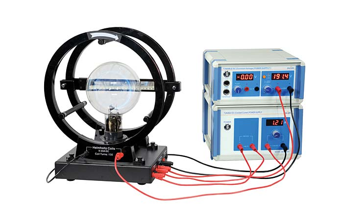</center>
<center>[_**Assembly for the measurement of the constant charge-mass with Helmholtz coils**_ ](https://www.pasco.com/images/products/se/SE9629_ENLRG_179474.jpg)</center>
With the use of an artifac (e/m) mark Pasco, model SE-9638, metric scale (appreciation: 1 mm), 2 sources of power (appreciation: 0.1 mA), a voltmeter (± 0.01 V) and ammeter (± 0.01 A), and some connector cables are built as shown in the previous image, consisting of a spherical glass container with low pressure helium, and inside it an electron gun formed by a filament that heats a material that acts as a cathode and a metal plate that acts as an anode.Between both electrodes we have a grid or grid that serves to control the passage of electrons to the anode, the grid is positive with respect to the cathode and negative with respect to the anode in order to help focus the beam of electrons that excite the helium atoms when colliding with them, radiating a greenish light that describes the trajectory of these particles. The pair of Helmholtz coils placed parallel with a distance equal to their radius of 15 cm,and with a number of turns of 130 for each one they provide a very uniform magnetic field in the central area between them which causes our electron beam to follow a circular path, whose radius can be measured with a graduated metric scale located transversely in one of the coils.
In the control panel, the sources and meters that adjust to the following levels are connected:
- **Low voltage source:** It serves so that the Helmholtz coils provide a constant magnetic field over time, this must be regulated between 6 and 9 Volts of direct current without exceeding the 2 amperes allowed.
- **Heating Source:**It is used to heat the filament, it must not exceed 6.3 VDC or VAC, because if it is exceeded, the material can be burned.
The data provided allows a good operation of the equipment whose installation is carried out with the following steps:
- The power supply and multimeters are connected to the control panel part of the Pasco brand (e / m) device, model SE-9638.
- At the left end of the panel we connect the ammeter, which in turn is connected to one of the power sources in order to measure the current intensity that enters the coils.
- In the center of the control panel we connect the voltmeter in parallel together with the power source to measure the voltage that accelerates the electrons.
- And on the far right is connected the power source that heats the electron gun.
For more information, see the following figure:
<center>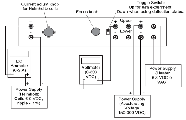</center>
<center>_**Figure 3**_</center>
Finally we proceed to activate the power source of the left end, the one that supplies current to the coil, to take measurements with constant intensities from 1 to 1.8 amperes, varying the voltage in each intensity, Likewise, the source that supplies the voltage that accelerates the electrons is activated, maintaining said constant amount from 220 **V** to 380 **V** and varying the intensity for each value of **V**.In both cases the length of the radius or diameter of the trajectory is measured as follows in the following figure.
<center>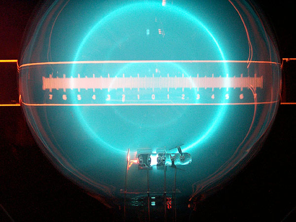</center>
<center>[_**Figura 4**_](http://helios.augustana.edu/physics/lab%20setup%20photos/352/img/measurement-of-e-over-m-for-electrons-2.jpg)</center>
As you can see in the previous figure, the length of the diameter of the electron path is fully visible, from which it is easy to obtain the radius. What is shown in this representation corresponds to the measure _**e/m**_ of the electron, using as theoretical basis the equation **(9)** and the instruments already described. In the next post I will show the results obtained for the constant using this method as well as certain relationships that can be deduced from the equation **(9)**. I hope this information has been of your interest and if you have any questions you can ask me or make any suggestions, thank you for your attention and the support provided
- - - -
References:
(1) Experimento e/m. F. Alberto Cardona-Maciel. Mayo 2010. Universidad de Gudalajara. Mexico
(2) Instruction Manual and Experiment Guidef or the PASCO scientific Model SE-9638. 1987 PASCO scientific.
(3) Physics 18L: Modern Physics Lab. Lab3: Measurement of e/m. Jacob Schwartz Partner: Tracy Ly. April2010. University of California, LosAngeles.
Figures 2 and 3 taken from the reference (1).
</div>