<div class="text-justify">The damping and filtering of electrical signals is a required process in communication systems or control systems when it comes to minimizing the effect of unwanted signals, such as noise or disturbances generated by the characteristics of the networks or external agents.</div> <p> <div class="text-justify">Figure 1 shows a circuit that has the mentioned properties and which is constituted by a resistor, a capacitor and an inductor in series so it is known as an <b>RCL circuit</b>.</div> <center>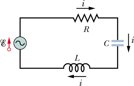</center> <center><em>Figure 1 - RCL series circuit [Image Source](http://www.pbx-brasil.com/outrasDisciplinas/FisIV/Notas/Iarea/aula106/figuras/fig2.jpg)</em></center> <div class="text-justify">Next, a brief theoretical analysis is developed to determine the behavior of the variables involved as a function of time and frequency. </div> <p> [Kirchhoff's Law](https://en.wikipedia.org/wiki/Kirchhoff%27s_circuit_laws) of Voltages allows obtaining the general expression that shows the temporal behavior of the variables. <center>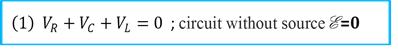</center> <em>V<sub>R</sub> → Resistance Voltage V<sub>C</sub> → Voltage in the capacitor V<sub>L</sub> → Voltage in the inductor</em> Where: <center>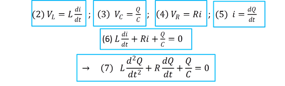</center> The solution of the differential equation is given by: <center>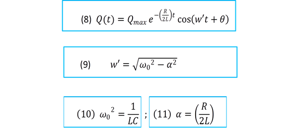</center> <em>ω<sub>0</sub> → Frequency resonant</em> <div class="text-justify">The angular frequency given by equation (9) is the main parameter used in the description and determination of the type of damping of the system and they are classified according to the value of the resistance.</div> <p> <center>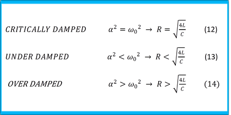</center> Figure 2 shows the different types of damping experienced by the electric charge that flows in the network. <center>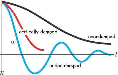</center> <center><em>Figure 2 - Types of damping [Image Source](http://www.cpp.edu/~skboddeker/132/notes/ch14_files/image014.jpg)</em></center> <h4>Experimental demonstration of the damping of a Signal in a Circuit R-C-L</h4> The following images show an experimental test carried out in the laboratory of the damping of a Square Signal that feeds an R-C-L circuit. R=8Ω ; L=2.2mH; C=100μf; V<sub>P-P</sub>= 5v <center>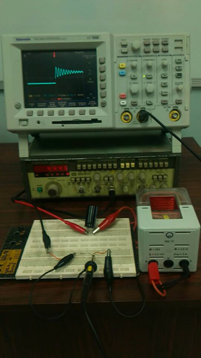</center> <center><em>Figure 3 - Test in the laboratory</em></center> <center>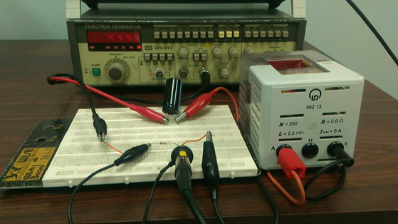</center> <center><em>Figure 4</em></center> <center>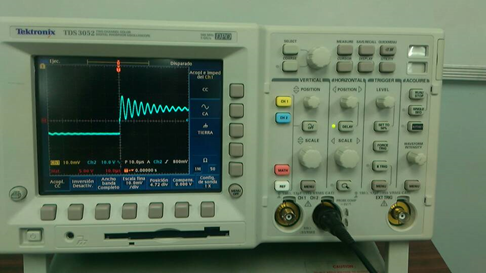</center> <center><em>Figure 5 - Square wave damped</em></center> <div class="text-justify">Signal filtering is another application of the R-C-L circuits. According to its configuration, the R-C-L circuits are classified according to the frequency range in which they allow the passage of a signal.</dib> <p> Figures 6, 7 and 8 show some of the most common configurations for signal filtering. <center>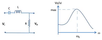</center> <center><em>Figure 6 - Band-Pass Filter Author @wilians - Microsoft Powerpoint</em></center> <center>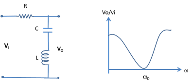</center> <center><em>Figure 7 - Notch Filter Author @wilians - Microsoft Powerpoint</em></center> <center>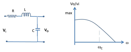</center> <center><em>Figure 8 - Low-Pass Filter Author @wilians - Microsoft Powerpoint</em></center> <div class="text-justify">In this way we can appreciate that in its simplest form an RLC circuit, formed by passive elements of low cost, allows the damping and filtering of electrical signals and whose applications have served to optimize the transmission and signal processing as well as the construction of high quality automated systems.</div> <h4>References</h4> * Automatic Control Systems. Farid Golnaraghi, Benjamin C. Kuo. Ninth edition. * Circuitos eléctricos. James W. Nilsson, Susan A. Riedel. 7ª. Edition. Pearson Prentice Hall. * Digital Signal Processing using MATLAB. Vinay K. Ingle, John G. Proakis. Third edition. * Fundamentals of Physics. Halliday & Resnick. Jearl Walker.10th. Edition. Wiley editorial.
| author | wilians |
|---|---|
| permlink | damping-and-filtering-of-signals-through-an-r-c-l-circuit |
| category | steemstem |
| json_metadata | {"tags":["steemstem","science","engineering","physics","curie"],"users":["wilians"],"image":["https://steemitimages.com/DQmS7m8KU5WdqyP493oyqDz9YzxyTNqVxGhNbRGDg9tUeLb/image.png","https://steemitimages.com/DQmd4TskQoJta1K7JMQ1uRuPnCPWJDA5uyZcPNp8tTcSmoB/image.png","https://steemitimages.com/DQmdKsfoXRJfnLrJNCk4PVtiLQVFTipoK8FUuaq1jFnc7io/image.png","https://steemitimages.com/DQmPrUEuNco5WG4VyqydUTjy52J45Y2eHw8nvumZhHKk7PL/image.png","https://steemitimages.com/DQmc3byzXCTdSC2XrWmsUiG1JTBnKWQKCDP7pSbc7YAsjVU/image.png","https://steemitimages.com/DQmWjj1UMBFJfwop4daWJpQ1mPLduaA48csc8qn4LYEBu6j/image.png","https://steemitimages.com/DQmY5DoVQFQ3GP5AV1W2QVhFxYVXXL4DZLNZNrmzUdpjEWN/image.png","https://steemitimages.com/DQmXYSh4aFAyexvzritAF5HUFuAMaxGuAR1NUVdpxL3VpRp/image.png","https://steemitimages.com/DQmTVTrjFPj7Yf3s3UE3uWhB3PmT7qkonfPyNVWb8cX73e1/image.png","https://steemitimages.com/DQmawCtjfiMdeARsZoVEPhaWKXBireJBMxbVkxjUE9ZnEjn/image.png","https://steemitimages.com/DQmcUZ3hYLiaT5LMAFfe3PhQQah2HkgnDf93DWrUwUEo1sP/image.png","https://steemitimages.com/DQmX5zN5ddqN2HAdBhEpbNHZYJpjmtjAWTCRsm9UVyKHad3/image.png"],"links":["http://www.pbx-brasil.com/outrasDisciplinas/FisIV/Notas/Iarea/aula106/figuras/fig2.jpg","https://en.wikipedia.org/wiki/Kirchhoff%27s_circuit_laws","http://www.cpp.edu/~skboddeker/132/notes/ch14_files/image014.jpg"],"app":"steemit/0.1","format":"markdown"} |
| created | 2018-02-10 16:58:54 |
| last_update | 2018-02-10 16:58:54 |
| depth | 0 |
| children | 2 |
| last_payout | 2018-02-17 16:58:54 |
| cashout_time | 1969-12-31 23:59:59 |
| total_payout_value | 0.396 HBD |
| curator_payout_value | 0.110 HBD |
| pending_payout_value | 0.000 HBD |
| promoted | 0.000 HBD |
| body_length | 4,821 |
| author_reputation | 1,081,379,506,886 |
| root_title | "Damping and Filtering of Signals through an R-C-L Circuit" |
| beneficiaries | [] |
| max_accepted_payout | 1,000,000.000 HBD |
| percent_hbd | 10,000 |
| post_id | 36,458,371 |
| net_rshares | 69,382,740,391 |
| author_curate_reward | "" |
| voter | weight | wgt% | rshares | pct | time |
|---|---|---|---|---|---|
| hr1 | 0 | 51,459,357,531 | 0.63% | ||
| qedqubit | 0 | 0 | 100% | ||
| lorenzor | 0 | 2,066,580,490 | 100% | ||
| rnunez09 | 0 | 8,585,963,410 | 100% | ||
| ufv | 0 | 894,753,847 | 100% | ||
| hugobohor | 0 | 3,850,647,681 | 100% | ||
| maeugenia | 0 | 1,334,964,842 | 100% | ||
| lawrencef | 0 | 616,838,484 | 100% | ||
| dexterdev | 0 | 573,634,106 | 100% |
These articles deserve more attention from people I guess. 😃 May be you can show some video related to how these circuits etc can be set up on breadboard. Just a suggestion.
| author | dexterdev |
|---|---|
| permlink | re-wilians-damping-and-filtering-of-signals-through-an-r-c-l-circuit-20180212t074207201z |
| category | steemstem |
| json_metadata | {"tags":["steemstem"],"app":"steemit/0.1"} |
| created | 2018-02-12 07:42:09 |
| last_update | 2018-02-12 07:42:09 |
| depth | 1 |
| children | 1 |
| last_payout | 2018-02-19 07:42:09 |
| cashout_time | 1969-12-31 23:59:59 |
| total_payout_value | 0.000 HBD |
| curator_payout_value | 0.000 HBD |
| pending_payout_value | 0.000 HBD |
| promoted | 0.000 HBD |
| body_length | 173 |
| author_reputation | 17,771,704,061,240 |
| root_title | "Damping and Filtering of Signals through an R-C-L Circuit" |
| beneficiaries | [] |
| max_accepted_payout | 1,000,000.000 HBD |
| percent_hbd | 10,000 |
| post_id | 36,869,220 |
| net_rshares | 0 |
Thanks for the suggestion and for reading the post, in other articles that i'll publish i'll show other configurations .
| author | wilians |
|---|---|
| permlink | re-dexterdev-re-wilians-damping-and-filtering-of-signals-through-an-r-c-l-circuit-20180213t205432192z |
| category | steemstem |
| json_metadata | {"tags":["steemstem"],"app":"steemit/0.1"} |
| created | 2018-02-13 20:54:33 |
| last_update | 2018-02-13 20:54:33 |
| depth | 2 |
| children | 0 |
| last_payout | 2018-02-20 20:54:33 |
| cashout_time | 1969-12-31 23:59:59 |
| total_payout_value | 0.000 HBD |
| curator_payout_value | 0.000 HBD |
| pending_payout_value | 0.000 HBD |
| promoted | 0.000 HBD |
| body_length | 120 |
| author_reputation | 1,081,379,506,886 |
| root_title | "Damping and Filtering of Signals through an R-C-L Circuit" |
| beneficiaries | [] |
| max_accepted_payout | 1,000,000.000 HBD |
| percent_hbd | 10,000 |
| post_id | 37,302,288 |
| net_rshares | 0 |