<center>

[ENG] Source by @alfonsoalfonsi made using CANVAS and image by [PxHere]( https://pxhere.com/es/photo/1639851?utm_content=clipUser&utm_medium=referral&utm_source=pxhere)
[SPA] Fuente por @alfonsoalfonsi realizado usando CANVAS e imagen de [PxHere]( https://pxhere.com/es/photo/1639851?utm_content=clipUser&utm_medium=referral&utm_source=pxhere)
</center>
<div class="text-justify">
<div class=pull-left>
#### Hello Hive Friends, continuing with theEmbedded System (ES) theme, I will present you the third part of this series, focused on the Software component, specifically the Embedded Software Architectures.
</div>
<div class=pull-right>
#### Hola Amigos de Hive, siguiendo con el tema de los Sistemas Empotrados o Embebidos (SE) les presentaré la tercera parte de esta serie, enfocada en el componente de Software, específicamente la Arquitecturas del Software Empotrado.
</div>
<hr>
<div class=pull-left>
In previous posts on <b>Embedded System with Style</b>, the [Part One: Concept and Context](https://hive.blog/hive-196387/@alfonsoalfonsi/eng-spa-sistema-empotrado-o-embebido-con-estilo-primera-parte-concepto-y-contexto-embedded-system-with-style-part-one-concept) and [Part Two: Architectural Style - Hardware](https://hive.blog/hive-196387/@alfonsoalfonsi/eng-spa-embedded-system-with-style-part-two-architectural-style-hardware-sistema-empotrado-o-embebido-con-estilo-segunda-parte) important definitions and common thread of the <b>Embedded Software</b> component were established.
</div>
<div class=pull-right>
En post anteriores de <b>Sistema Empotrado o Embebido con Estilo</b>, la [Primera Parte: Concepto y Contexto](https://hive.blog/hive-196387/@alfonsoalfonsi/eng-spa-sistema-empotrado-o-embebido-con-estilo-primera-parte-concepto-y-contexto-embedded-system-with-style-part-one-concept) y la [Segunda Parte: Estilo Arquitectónico – Hardware](https://hive.blog/hive-196387/@alfonsoalfonsi/eng-spa-embedded-system-with-style-part-two-architectural-style-hardware-sistema-empotrado-o-embebido-con-estilo-segunda-parte) se establecieron definiciones importantes e hilo conductor del componente <b>Software Empotrado</b>.
</div>
<hr>
<div class=pull-left>
In addition, two development directions were pointed out, one with low computational processing, and the other, where real-time operation facilities, energy adjustment management, high signal processing performance, etc., <b>Conventional Embedded Software</b> and <b>Advanced</b>, respectively, should be provided.
</div>
<div class=pull-right>
Además se señalaron dos vertientes de desarrollo, una con bajo procesamiento computacional, y otra, donde deben otorgarse facilidades de operación en tiempo real, manejo del ajuste de energías, altas prestaciones de procesamiento de señales, etc., <b>Software Empotrado Convencional</b> y <b>Avanzado</b>, respectivamente.
</div>
<center>

</center>
<div class=pull-left>
### PRELIMINARY
</div>
<div class=pull-right>
### PRELIMINARES
</div>
<center>

</center>
<div class="text-justify">
<div class=pull-left>
The basic phases for embedded software development are the <b>Software Architecture</b>, which is then documented and advanced until it becomes the final application of the system, which is why it is considered in the literature as a system design plan.
</div>
<div class=pull-right>
En las fases básicas para el desarrollo software empotrado se encuentra el diseño de la <b>Arquitectura del Software</b>, que luego va documentándose y avanzando hasta convertirse en la aplicación final del sistema, razón por la cual en la literatura es considerada como plan de diseño del sistema.
</div>
<hr>
<div class=pull-left>
The architecture is preceded only by the system requirements, which form the basis for decisions about the overall architecture. And, such decisions, in turn, constrain the software architecture.
</div>
<div class=pull-right>
A la arquitectura solo le antecede los requisitos del sistema, que forman la base para las decisiones sobre la arquitectura general. Y, tales decisiones limitan a su vez la arquitectura del software.
</div>
<center>

</center>
<div class=pull-left>
### Definition
</div>
<div class=pull-right>
### Definición
</div>
<center>

</center>
<div class="text-justify">
<div class=pull-left>
[ISO/IEC/IEEE 42010:2011](https://www.iso.org/standard/50508.html) defines:
</div>
<div class=pull-right>
La norma [ISO/IEC/IEEE 42010:2011](https://www.iso.org/standard/50508.html) define:
</div>
<div class=pull-left>
<blockquote>
<i><b>Software architecture is the fundamental organization of a system formed by its components, the relationships between them and the context in which they will be implemented, and the principles that guide their design and evolution.</b></i>
</blockquote>
</div>
<div class=pull-right>
<blockquote>
<i><b>Arquitectura del Software es la organización fundamental de un sistema formada por sus componentes, las relaciones entre ellos y el contexto en el que se implantarán, y los principios que orientan su diseño y evolución.</b></i>
</blockquote>
</div>
<hr>
<div class=pull-left>
That is, on the one hand, it defines the <b>system structure</b>, which is made up of components, modules or pieces of code that are born from the notion of abstraction, fulfilling specific functions, and interacting with each other with defined behavior.
</div>
<div class=pull-right>
Es decir, por un lado define la <b>estructura del sistema</b>, que está constituida de componentes, módulos o piezas de código que nacen de la noción de abstracción, cumpliendo funciones específicas, e interactuando entre sí con un comportamiento definido.
</div>
<hr>
<div class=pull-left>
The components allow, at the design level, to make the necessary decisions during the construction of a software system.
</div>
<div class=pull-right>
Los componentes permiten, a nivel de diseño, tomar las decisiones necesarias durante la construcción de un sistema de software.
</div>
<hr>
<div class=pull-left>
In addition, the choice of the appropriate architecture must provide the desired functionality and quality attributes. It is basically determined by quality criteria such as modifiability, maintainability, security, and performance.
</div>
<div class=pull-right>
Además, la elección de la arquitectura adecuada debe proporcionar la funcionalidad deseada y atributos de calidad. Es determinada básicamente por criterios de calidad como la modificabilidad, mantenibilidad, seguridad y el rendimiento.
</div>
<center>

</center>
<div class=pull-left>
### A LOOK AT SYSTEM REQUIREMENTS
</div>
<div class=pull-right>
### PINCELADA A LOS REQUERIMIENTOS DEL SISTEMA
</div>
<center>

</center>
<div class="text-justify">
<div class=pull-left>
In the literature on <b>Software Engineering</b>, authors such as [Roger S. Pressman]( https://en.wikipedia.org/wiki/Roger_S._Pressman) maintain that there are two kinds of models: requirements and design models.
</div>
<div class=pull-right>
En la literatura acerca de la <b>Ingeniería de Software</b>, autores como [Roger S. Pressman]( https://en.wikipedia.org/wiki/Roger_S._Pressman) mantienen que hay dos clases de modelos: de requerimientos y de diseño.
</div>
<hr>
<div class=pull-left>
The former, represent customer requirements in three domains: information, functional and behavioral; design models are software features that help to effectively elaborate: architecture, user interface, and component-level detail (Pressman & Maxim, 2019).
</div>
<div class=pull-right>
Los primeros, representan los requerimientos del cliente en tres dominios: información, funcional y comportamiento; los modelos de diseño son características del software que ayudan a elaborar con eficacia: arquitectura, interfaz de usuario y detalle en el nivel de componente (Pressman y Maxim, 2019).
</div>
<hr>
<div class=pull-left>
That is, many things must be specified and documented in a software project. There are functional and non-functional requirements. These aspects of information capture are taken care of by <b>Requirements Engineering</b> which is a branch of <b>Software Engineering</b>.
</div>
<div class=pull-right>
Es decir, muchas cosas se deben especificar y documentar en un proyecto software. Están, los requisitos funcionales y no funcionales. Estos aspectos de captura de información son atendidos por la <b>Ingeniería de Requisitos</b> que es una rama de la <b>Ingeniería de Software</b>.
</div>
<hr>
<div class=pull-left>
In this post, I will not go deep into this topic because it is quite extensive and one should be careful when approaching it. However, good documentation can be found in several texts (Pressman & Maxim, 2019; Sommerville, 2018) or, in the standard [ISO/IEC/IEEE 29148:2018](https://www.iso.org/standard/72089.html).
</div>
<div class=pull-right>
En este post no voy a profundizar en este tópico, porque es bastante extenso y se debe ser cuidadoso al plantearlo. No obnstante, una buena documentación la pueden encontrar en varios textos (Pressman y Maxim, 2019; Sommerville, 2018) o, en la norma [ISO/IEC/IEEE 29148:2018](https://www.iso.org/standard/72089.html).
</div>
<hr>
<div class=pull-left>
In ESs the above becomes more acute, because having restrictions of size, weight, energy autonomy, real-time, to name a few, the developer must be prepared to determine them. Be it for <b>Conventional Embedded Software</b> or <b>Advanced</b>, providing the desired functionality and quality attributes.
</div>
<div class=pull-right>
En los SE lo anterior se agudiza, porque al tener restricciones de tamaño, peso, autonomía energética, tiempo real, por nombrar algunas, el desarrollador debe prepararse para determinarlas. Sean para el <b>Software Empotrado Convencional</b> o <b>Avanzado</b>, proporcionando la funcionalidad deseada y atributos de calidad.
</div>
<center>

</center>
<div class=pull-left>
### TAXONOMY
</div>
<div class=pull-right>
### TAXONOMÍA
</div>
<center>

</center>
<div class="text-justify">
<div class=pull-left>
Here I will indicate the taxonomy of Architectural Style presented by Pressman (2010) which is taken to the ES.
</div>
<div class=pull-right>
Aquí indicaré la taxonomía del Estilo Arquitectónico que presenta Pressman (2010) el cual es llevado a los SE.
</div>
<hr>
<div class=pull-left>
<b>1. Data Centered.</b>
</div>
<div class=pull-right>
<b>1. Centrada en los Datos.</b>
</div>
<hr>
<div class=pull-left>
At the center of this architecture is a data storage that is frequently accessed by other components that update, add, delete or modify data in some way within the storage (Figure 1).
</div>
<div class=pull-right>
En el centro de esta arquitectura se halla un almacenamiento de datos al que acceden con frecuencia otros componentes que actualizan, agregan, eliminan o modifican los datos de cierto modo dentro del almacenamiento (Figura 1).
</div>
<hr>
<div class=pull-left>
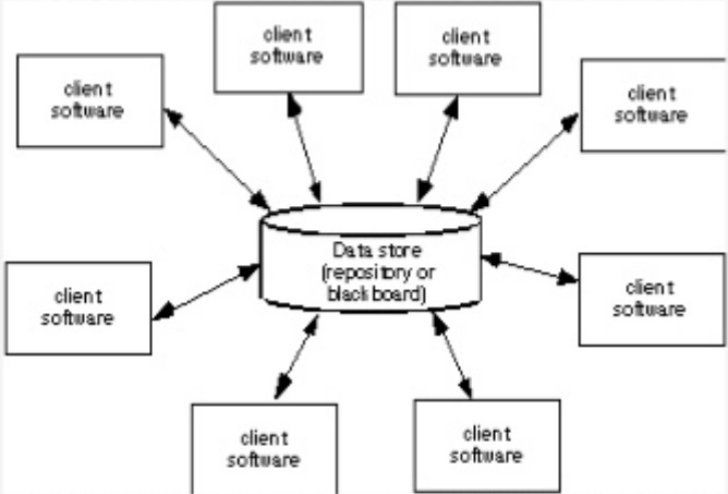
<sup>Figure 1. Data-Centred Architectural Style. Source: Pressman (2010, Chapter 9)</sup>
</div>
<div class=pull-right>
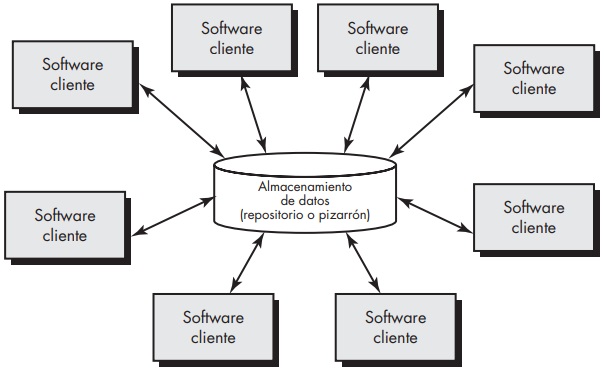
<sup>Figura 1. Estilo Arquitectónico Centrada en los datos. Fuente: Pressman (2010, Capítulo 9)</sup>
</div>
<hr>
<div class=pull-left>
<b>2. Data Flow.</b>
</div>
<div class=pull-right>
<b>2. De Flujo de Datos.</b>
</div>
<hr>
<div class=pull-left>
The system is viewed as a series of transformations through a series of computational components or manipulators The data enters the system and flows between the components, one at a time until it is assigned a final destination (Figure 2).
</div>
<div class=pull-right>
El sistema es visto como una serie de transformaciones a través de una serie de componentes computacionales o manipuladores El dato ingresa en el sistema, y fluye entre los componentes, de uno en uno, hasta que se le asigne un destino final (Figura 2).
</div>
<hr>
<div class=pull-left>
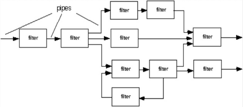
<sup>Figure 2. Architectural style of data flow. Source: Pressman (2010, Chapter 9)</sup>
</div>
<div class=pull-right>
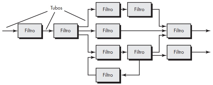
<sup>Figura 2. Estilo Arquitectónico de flujo de datos. Fuente: Pressman (2010, Capítulo 9)</sup>
</div>
<hr>
<div class=pull-left>
<b>3. Call and Return.</b>
</div>
<div class=pull-right>
<b>3. De Llamar y Regresar.</b>
</div>
<hr>
<div class=pull-left>
The system consists of the main program that has control of the system and several subprograms that communicate with it through the use of calls. Within this category, there are several sub-styles, such as Main Program/Sub-Program Architectures and Remote Procedure Call Architectures (Figure 3).
</div>
<div class=pull-right>
El sistema se constituye de un programa principal que tiene el control del sistema y varios subprogramas que se comunican con éste mediante el uso de llamadas. Dentro de esta categoría existen varios subestilos, como las Arquitecturas de programa principal/subprograma y Arquitecturas de llamada de procedimiento remoto (Figura 3).
</div>
<hr>
<div class=pull-left>
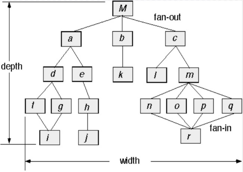
<sup>Figure 3. The architectural style of call and return. Source: Pressman (2010, Chapter 9)</sup>
</div>
<div class=pull-right>
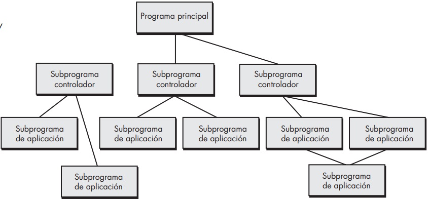
<sub>Figura 3. Estilo Arquitectónico de llamar y regresar. Fuente: Pressman (2010, Capítulo 9)</sub>
</div>
<hr>
<div class=pull-left>
<b>4. Object-Oriented Architectures</b>.
</div>
<div class=pull-right>
<b>4. Arquitecturas Orientadas a Objetos.</b>
</div>
<hr>
<div class=pull-left>
The components of a system include data and the operations that must be applied to manipulate them. Communication and coordination between the components are achieved through the transmission of messages.
</div>
<div class=pull-right>
Los componentes de un sistema incluyen datos y las operaciones que deben aplicarse para manipularlos. La comunicación y coordinación entre los componentes se consigue mediante la transmisión de mensajes.
</div>
<hr>
<div class=pull-left>
<b>5. Layered.</b>
</div>
<div class=pull-right>
<b>5. En capas.</b>
</div>
<hr>
<div class=pull-left>
In the basic structure of a layered architecture, several different layers are defined; each layer executes operations that progressively approximate the machine instruction set.
</div>
<div class=pull-right>
En la estructura básica de una arquitectura en capas, se define un número de capas diferentes; cada una ejecuta operaciones que se aproximan progresivamente al conjunto de instrucciones de máquina.
</div>
<hr>
<div class=pull-left>
In the outer layer, components serve the user interface operations. At the internal layer, components interface with the operating system. The middle layers provide utility services and application software functions (Figure 4).
</div>
<div class=pull-right>
En la capa externa, los componentes atienden las operaciones de la interfaz de usuario. En la interna, los componentes realizan la interfaz con el sistema operativo. Las capas intermedias proveen servicios de utilerías y funciones de software de aplicación (Figura 4).
</div>
<hr>
<div class=pull-left>
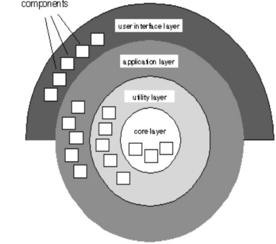
<sup>Figure 4. Layered Architectural Style. Source: Pressman (2010, Chapter 9)</sup>
</div>
<div class=pull-right>
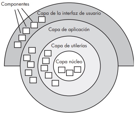
<sup>Figura 4. Estilo Arquitectónico en capas. Fuente: Pressman (2010, Capítulo 9)</sup>
</div>
<center>

</center>
<div class=pull-left>
### EXAMPLE
</div>
<div class=pull-right>
### EJEMPLO
</div>
<center>

</center>
<div class="text-justify">
<div class=pull-left>
<b><i>Purpose</i></b>.
</div>
<div class=pull-right>
<b><i>Planteamiento</i></b>.
</div>
<hr>
<div class=pull-left>
We want to design an ES based on Microcontroller, which measures two (2) magnitudes coming from two (2) temperature sensors. The values are averaged and the result is prepared for a communication link with a Desktop Computer, besides presenting the data of such activity is an indicator that has the ES. The information will contain Identification of the activity (1, 2, ..., N), Sensor 1 Temperature, Sensor 2 Temperature, Average Temperature obtained. In addition, there is a switch that activates or deactivates the system.
</div>
<div class=pull-right>
Se quiere diseñar un SE basado en Microcontrolador, que mide dos (2) magnitudes que provienen de dos (2) sensores de temperatura. Los valores son promediados y el resultado es preparado para un enlace de comunicación con un Computador de Escritorio, además de presentar los datos de dicha actividad en un indicador que posee el SE. La información contendrá: Identificación de la actividad (1, 2, …, N), Temperatura del Sensor 1, Temperatura del Sensor 2, Promedio de la Temperatura obtenida. Además, hay un interruptor que activa o desactiva el sistema.
</div>
<hr>
<div class=pull-left>
For this purpose there is a <b>Hypothetical Processor (HP)</b> that has resources for digital and analog communication (<b>I/O ports</b>), <b>I2C</b>, <b>communication port</b> via USB, works at an operating frequency <b>F MHz</b> and is powered with a voltage level of <b>V</b>, it also has memory to house both embedded program code, interrupt handling and any other basic facilities of this type of device.
</div>
<div class=pull-right>
Para tal fin se tiene un <b>Procedor Hipotético (PH)</b> que posee recursos para la comunicación digital y analógica (<b>Puertos I/O</b>), (<b>I2C</b>), <b>puerto de comunicación</b> vía USB, trabaja a una frecuencia de operación <b>F MHz</b> y está alimentado con un nivel de voltaje de <b>V</b>, además tiene memoria para alojar tanto el código del programa empotrado, manejo de interrupciones y cualquier otra facilidad básica de este tipo de dispositivo.
</div>
<hr>
<div class=pull-left>
It is worth noting that here we will not analyze the Hardware and Software Architectures that give a feasible and achievable solution to the problem. For this, it is necessary to survey their requirements. We will only discuss the different alternatives of the solution, highlighting some of its characteristics.
</div>
<div class=pull-right>
Vale la pena destacar, que aquí no se analizarán las Arquitecturas de Hardware y Software que dan una solución factible y realizable al problema. Para esto hay que hacer un levantamiento de sus requerimientos. Solo discutiremos las diferentes alternativas de la solución, destacando algunas de sus características.
</div>
<hr>
<div class=pull-left>
<b><i>Traditional Hardware and Call and Return Software Architecture</i></b>
</div>
<div class=pull-right>
<b><i>Arquitectura de Hardware Tradicional y de Software de Llamar y Regresar</i></b>
</div>
<hr>
<div class=pull-left>
From the approach, the <b>Traditional Hardware Architecture</b> for the Example is presented (Figure 5), where the HP resources are leveraged to satisfy the approach.
</div>
<div class=pull-right>
Del planteamiento se presenta la <b>Arquitectura de Hardware Tradicional</b> para el Ejemplo (Figura 5), donde se aprovecha los recursos del PH para satisfacer el planteamiento.
</div>
<hr>
<div class=pull-left>
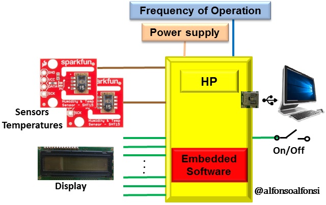
<sup>Figure 5. Traditional Hardware Architecture of the Example System</sup>.
</div>
<div class=pull-right>
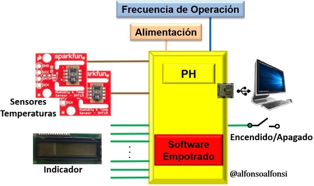
<sup>Figura 5. Arquitectura de Hardware Tradicional del Sistema Ejemplo.</sup>
</div>
<hr>
<div class=pull-left>
Then:
</div>
<div class=pull-right>
Entonces:
</div>
<hr>
<div class=pull-left>
<li>Two (2) Temperature Sensors communicate through two (2) HP Analog Input Ports.</li>
<hr>
<li>One (1) indicator connects to the HP's digital output ports.</li>
<hr>
<li>The HP has a USB port which is used for communication with the Personal Computer.</li>
<hr>
<li>It has a built-in on/off switch.</li>
</div>
<div class=pull-right>
<li>Dos (2) Sensores de Temperatura se comunican por dos (2) Puertos de Entrada Analógicos del PH.</li>
<hr>
<li>Un (1) indicador se conecta a Puertos digitales de salida del PH.</li>
<hr>
<li>El PH tiene un puerto USB el cual se utiliza para la comunicación con el Computador Personal.</li>
<hr>
<li>Tiene incorporado un conmutador de encendido y apagado.</li>
</div>
<hr>
<div class=pull-left>
Now, the specifications for the <b>Call and Return Software Architecture</b> must be created (Figure 6).
</div>
<div class=pull-right>
Ahora, se debe crear las especificaciones para la <b>Arquitectura de Software de Llamar y Regresar</b> (Figura 6).
</div>
<hr>
<div class=pull-left>
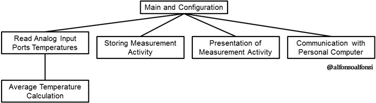
<sub>Figure 6. Example System Call and Return Software Architecture.</sub>
</div>
<div class=pull-right>
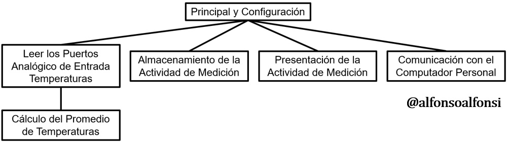
<sup>Figura 6. Arquitectura de Software de Llamada y Regresar del Sistema Ejemplo.</sup>
</div>
<hr>
<div class=pull-left>
For this purpose, the basic requirements are:
</div>
<div class=pull-right>
Para ello, los requerimientos básicos son:
</div>
<hr>
<div class=pull-left>
<li>Read the magnitudes of the two (2) Temperature Sensors and fit them to the microcontroller, these must be averaged and the result is stored. At this point, there is no further specification if it should store in memory or an internal register of the microcontroller, so we will store it in memory.</li>
</div>
<div class=pull-right>
<li>Leer las magnitudes de los dos (2) Sensores de Temperatura y adecuarlos al microcontrolador, estos deben ser promediados y el resultado se almacena. En este punto, no hay más especificación si debe almacenar en memoria o en un registro interno del microcontrolador, así que lo almacenaremos en memoria. </li>
</div>
<hr>
<div class=pull-left>
<li>The result is accompanied by the Activity ID (1, 2, ... , N), Sensor 1 Temperature and Sensor 2 Temperature.</li>
</div>
<div class=pull-right>
<li>Al resultado lo acompañan la Identificación de la actividad (1, 2, … , N), Temperatura del Sensor 1 y Temperatura del Sensor 2.</li>
</div>
<hr>
<div class=pull-left>
<li>This information is prepared for the communication link provided by the Microcontroller via USB to the Personal Computer.</li>
</div>
<div class=pull-right>
<li>Esta Información se prepara para el enlace de comunicación previsto por el Microcontrolador vía USB hacia el Computador Personal.</li>
</div>
<hr>
<div class=pull-left>
<li>Of course, the ES of the Example must be active, i.e. energized.</li>
</div>
<div class=pull-right>
<li>Por supuesto, el SE del Ejemplo debe estar activo, es decir energizado.</li>
</div>
<hr>
<div class=pull-left>
Actually, other connections could be made in the modules indicated in the architecture, so it is not the only solution. This then becomes a function-based code, which is common among programmers.
</div>
<div class=pull-right>
Realmente, se podría hacer otras conexiones en los módulos señalados en la arquitectura, por tanto no es la única solución. Esto luego se transforma en un código basado en funciones, lo cual es común entre programadores.
</div>
<hr>
<div class=pull-left>
<b><i>Traditional Hardware and Object-Oriented Software Architecture.</i></b>
</div>
<div class=pull-right>
<b><i>Arquitectura de Hardware Tradicional y de Software Orientada a Objetos.</i></b>
</div>
<hr>
<div class=pull-left>
An <b>Object Oriented Software Architecture</b> can be proposed. Of course, for this, everything concerning object-orientation must be understood and handled. Nowadays, microcontrollers and their software facilities help a lot to establish this kind of architecture.
</div>
<div class=pull-right>
Se puede proponer una <b>Arquitectura de Software Orientada a Objetos</b>. Por supuesto que para ello se debe entender y manejar todo lo concerniente a la orientación objeto. En la actualidad, los microcontroladores y sus facilidades de software ayudan mucho a establecer este tipo de arquitecturas.
</div>
<hr>
<div class=pull-left>
Of course, a simple example is taken here for exemplification and I use a notation employed in this context called Unified Modeling Language (UML) (Pressman & Maxim, 2019; Sommerville, 2018).
</div>
<div class=pull-right>
Por supuesto, aquí se toma un ejemplo sencillo para ejemplificar y utilizo una notación empleada en este contexto llamada Lenguaje Unificado de Modelado (UML: Unified Modeling Language) (Pressman & Maxim, 2019; Sommerville, 2018).
</div>
<hr>
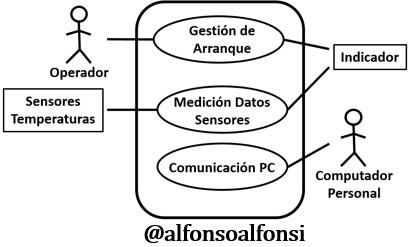
<div class=pull-left>
Figure 7 depicts the Example General Use Case Diagram to express the behavior of the system. These diagrams model system functionality using actors and use cases. Use cases are services or functions provided by the system for its users.
</div>
<div class=pull-right>
En la Figura 7 se representa el Diagrama de Caso Uso General del Ejemplo para expresar el comportamiento del sistema. Estos diagramas modelan la funcionalidad del sistema usando actores y casos de uso. Los casos de uso son servicios o funciones provistas por el sistema para sus usuarios.
</div>
<hr>
<div class=pull-left>
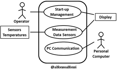
<sub>Figure 7. Object-Oriented Software Architecture. General Use Case of the Example.</sub>
</div>
<div class=pull-right>
<sup>Figura 7. Arquitectura de Software Orientada a Objetos. Caso de Uso General del Ejemplo.</sup>
</div>
<hr>
<div class=pull-left>
The General Use Case Diagram of the Example highlights the behavior of the system, where Actors such as the <b>Operator</b> that manages the system and <b>Personal Computer</b> to which the information generated by the system is sent, have roles and characteristics that must be written in detail.
</div>
<div class=pull-right>
En el Diagrama de Caso Uso General del Ejemplo se destaca el comportamiento del sistema, donde Actores como el <b>Operador</b> que maneja el sistema y <b>Computador Personal</b> al cual se le envía la información generada por el sistema, tiene roles y características que se deben escribir en detalle.
</div>
<hr>
<div class=pull-left>
Likewise, there are the <b>Indicator</b>, the output device that consumes the information generated by the system, and <b>Temperature Sensors</b> that represent the transducers that feed the data to the system.
</div>
<div class=pull-right>
Así mismo, está el <b>Indicador</b>, dispositivo de salida que consume la información generada por el sistema, y <b>Sensores de Temperatura</b> que representa los transductores que alimentan los datos al sistema.
</div>
<hr>
<div class=pull-left>
Three (3) use cases are also indicated, which can be detailed to meet the specifications of the system, being these:
</div>
<div class=pull-right>
También se indican tres (3) casos de uso, los cuales pueden ser detallados para llegar a cumplir las especificaciones del sistema, siendo estos:
</div>
<hr>
<div class=pull-left>
<li><b>Startup Management</b>: here are materialized the software components required to start the system and set its configuration, as well as to deactivate it.</li>
</div>
<div class=pull-right>
<li><b>Gestión de Arranque</b>: aquí se materializan los componentes de software necesario para iniciar el sistema y establecer su configuración, así como también, desactivarlo.</li>
</div>
<hr>
<div class=pull-left>
<li><b>Data Measurement</b>: this use case can be expanded and detailed, as it deals with the magnitudes of the two (2) Temperature Sensors and adapt them for processing. It calculates the required average of the temperatures. It generates the activity information. The result is stored in locations in the internal memory of the HP. It also sends the activity information to the Indicator.</li>
</div>
<div class=pull-right>
<li><b>Medición de Datos</b>: este caso de uso puede expandirse y detallarse, ya que trata las magnitudes de los dos (2) Sensores de Temperatura y adecuarlos para su procesamiento. Hace el cálculo del promedio requerido de las temperaturas. Genera la información de la actividad. El resultado se almacena en localidades en memoria interna del PH. También envía la información de la actividad al Indicador.</li>
</div>
<hr>
<div class=pull-left>
<li><b>Communication PC</b>: its role is to take the activity information and prepare it to send it to the Personal Computer.</li>
</div>
<div class=pull-right>
<li><b>Comunicación PC</b>: su rol es tomar la información de la actividad y prepararla para enviarla al Computador Personal.</li>
</div>
<hr>
<div class=pull-left>
It is worth noting that the modeling is done through several diagrams that visually show the characteristics of the embedded software. Together they form the Software Architecture.
</div>
<div class=pull-right>
Vale la pena destacar que el modelado se realiza a través de varios diagramas que muestran visualmente características del software empotrado. En su conjunto forman la Arquitectura de Software.
</div>
<hr>
<div class=pull-left>
For example, using the UML, you will find two subsets called structural and behavioral diagrams, each with its own function, which together allow the understanding of the system software as a whole.
</div>
<div class=pull-right>
Por ejemplo utilizando el UML, se encontrarán dos subconjuntos llamados diagramas estructurales y de comportamiento, cada uno con su propia función, que en conjunto permiten la comprensión del software del sistema como un todo.
</div>
<hr>
<div class=pull-left>
A comparison of why to use several views to express a system is a building, it is not possible to elaborate a single plan containing all the details, several are elaborated to represent the different aspects.
</div>
<div class=pull-right>
Una comparación del por qué usar varias vistas para expresar un sistema es una edificación, no es posible elaborar un solo plano que contenga todos los detalles, se elaboran varios que representan los diferentes aspectos.
</div>
<hr>
<div class=pull-left>
At this point, it would be worth asking the question: if I opt for another Hardware Architecture, how would the Software Architecture look like, could I use the diagram in Figure 7 in another architecture? A good exercise.
</div>
<div class=pull-right>
En este punto, valdría la pena preguntarse ¿si opto por otra Arquitectura de Hardware, cómo quedaría la de Software?, ¿podría usar el diagrama de la figura 7 en otra arquitectura? Un buen ejercicio.
</div>
<center>

</center>
<div class=pull-left>
### EMBEDDED SOFTWARE COMPONENT
</div>
<div class=pull-right>
### COMPONENTE DE SOFTWARE EMPOTRADO
</div>
<center>

</center>
<div class="text-justify">
<div class=pull-left>
While it is true that in the software architecture the respective models of what will be the system are made, its implementation is another matter. Therefore, the original concept of Software Architecture lies in Architectural Design.
</div>
<div class=pull-right>
Si bien es cierto, que en la arquitectura de software se hacen los respectivos modelos de lo que será el sistema, su implementación es otro asunto. Por tanto, el concepto original de la Arquitectura de Software recae en el Diseño Arquitectónico.
</div>
<hr>
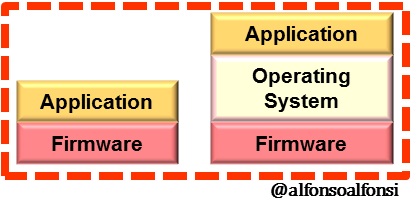
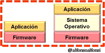
<div class=pull-left>
Reflecting the above in Figure 8, the Architecture is the basis for the <b>Firmware</b> and the <b>Application</b> since the design and implementation will follow what is detailed in it. When in an ES there is the possibility of having an <b>Operating System</b>, this will be part of the facilities and resources available to the system, even if it is a micro or nanocore.
</div>
<div class=pull-right>
Reflejando lo anterior en la Figura 8, la Arquitectura es la base para el <b>Firmware</b> y la <b>Aplicación</b> ya que el diseño e implementación seguirá lo detallado en esta. Cuando en un SE hay la posibilidad de tener un <b>Sistema Operativo</b> pues este formará parte de las facilidades y recursos con que cuenta el sistema, aun cuando sea un micronúcleo o nanonúcleo.
</div>
<hr>
<div class=pull-left>
<sub>Figure 8. Embedded Software Component. Source: [@alfonsoalfonsi](https://hive.blog/hive-196387/@alfonsoalfonsi/eng-spa-sistema-empotrado-o-embebido-con-estilo-primera-parte-concepto-y-contexto-embedded-system-with-style-part-one-concept)</sub>
</div>
<div class=pull-right>
<sub>Figura 8. Componente de Software Empotrado. Fuente: [@alfonsoalfonsi](https://hive.blog/hive-196387/@alfonsoalfonsi/eng-spa-sistema-empotrado-o-embebido-con-estilo-primera-parte-concepto-y-contexto-embedded-system-with-style-part-one-concept)</sub>
</div>
<hr>
<div class=pull-left>
Increasingly, there are ES's that host Operating Systems with very good features. The Smart Phone is a good example of this.
</div>
<div class=pull-right>
Cada vez más, hay SE que alojan Sistemas Operativos con muy buenas prestaciones. El Teléfono Inteligente es un buen ejemplo de ello.
</div>
<hr>
<div class=pull-left>
Currently, SE Architectures are incorporating methodologies, technologies, and standards that enthusiasts in this field should always consult. Therefore, I point you to Taylor and Taylor (2021), Voigtmann GmbH (2021), and Lacamare (2018) among some references that might be useful to keep you up to date.
</div>
<div class=pull-right>
Actualmente, las Arquitecturas de los SE van incorporando metodologías, tecnologías y normas que los entusiastas de este campo siempre deben consultar. Por tanto, les indico a Taylor y Taylor (2021), Voigtmann GmbH (2021) y Lacamare (2018) entre algunas referencias que pudieran servirles para mantenerse al día.
</div>
<center>

</center>
<div class="text-justify">
<div class=pull-left>
### CLOSING PART THREE
</div>
<div class=pull-right>
### CIERRE DE LA TERCERA PARTE
</div>
<center>

</center>
<div class="text-justify">
<div class=pull-left>
The <b>Embedded Software Architecture</b> is documented and advanced until it becomes the final application of the system, which is why it is considered in the literature as a system design plan.
</div>
<div class=pull-right>
La <b>Arquitectura del Software Empotrado</b> va documentándose y avanzando hasta convertirse en la aplicación final del sistema, razón por la cual en la literatura es considerada como plan de diseño del sistema.
</div>
<hr>
<div class=pull-left>
The architecture is preceded only by the system requirements, which form the basis for decisions about the overall architecture. And, such decisions, in turn, constrain the software architecture. In addition, the choice of the appropriate architecture must provide the desired functionality and quality attributes.
</div>
<div class=pull-right>
A la arquitectura solo le antecede los requisitos del sistema, que forman la base para las decisiones sobre la arquitectura general. Y, tales decisiones limitan a su vez la arquitectura del software. Además, la elección de la arquitectura adecuada debe proporcionar la funcionalidad deseada y atributos de calidad.
</div>
<hr>
<div class=pull-left>
Therefore, I invite ES developers to use all the tools and facilities provided by current technologies.
</div>
<div class=pull-right>
Por tanto, aquellos desarrolladores de SE les invito a utilizar todas las herramientas y facilidades que nos otorgan las tecnologías actuales.
</div>

<div class=pull-left>
<i>See you soon HIVE friends, I hope you liked this post.</i>
</div>
<div class=pull-right>
<i>Nos vemos pronto amigos HIVE, espero que les haya gustado este post.</i>
</div>
<hr>
<div class=pull-left>
<i>Thank you for your time and comments.</i>
</div>
<div class=pull-right>
<i>Gracias por su tiempo y comentarios.</i>
</div>
<center>

### REFERENCES / REFERENCIAS
</center>
<div class="text-justify">
Alfonsi, A. [@alfonsoalfonsi] (2021, June 4). [Eng-Spa] Embedded Systems with Style. Part Two: Arquitectonic Style-Hardware. The HiVE Blog. [POST]. https:// https://hive.blog/hive-196387/@alfonsoalfonsi/eng-spa-embedded-system-with-style-part-two-architectural-style-hardware-sistema-empotrado-o-embebido-con-estilo-segunda-parte
Alfonsi, A. [@alfonsoalfonsi] (2021, May 29). [Eng-Spa] Embedded Systems with Style. Part One: Concept and Context. The HiVE Blog. [POST]. https://hive.blog/hive-196387/@alfonsoalfonsi/eng-spa-sistema-empotrado-o-embebido-con-estilo-primera-parte-concepto-y-contexto-embedded-system-with-style-part-one-concept
ISO/IEC/IEEE (2011). ISO/IEC/IEEE 42010:2011 - ISO/IEC/IEEE Systems and Software Engineering - Architecture Description. https://www.iso.org/standard/50508.html
ISO/IEC/IEEE (2018). ISO/IEC/IEEE 29148:2018. Systems and software engineering-Life cycle processes -- Requirements engineering. https://www.iso.org/standard/72089.html
Lacamare, D. (2018). Embedded Systems Architecture: Explore architectural concepts, pragmatic design patterns, and best practices to produce robust systems. Packt Publishing.
Pressman, R. S. & Maxim, B. R. (2019). Software Engineering: A Practitioner's Approach (9th ed.). McGraw-Hill Education.
Pressman, R. S. (2010). Software Engineering: A Practitioner's Approach (7th ed.). McGraw-Hill Higher Education.
Pressman, R. S. (2010). Ingeniería de Software:Un Enfoque Práctico (7a ed.). McGraw-Hill Interamericana Editores S.A. de C.V.
Sommerville, I. (2018). Software Engineering (10a ed.). Pearson India.
Taylor, J. T. & Taylor, W. T. (2021). Patterns in the Machine: A Software Engineering Guide to Embedded Development. Apress.
Voigtmann GmbH. (2021). Software architecture. Consultado el 28 de octubre de 2019.
https://www.voigtmann.de/en/app-development/software-architecture/
</div>
<hr>
<center>
### Figures/ Figuras
</center>
<div class="text-justify">
<div class=pull-left>
Figures 1, 2, 3, and 4 are from Pressman's book (2010, Chapter 9) and were adjusted using Paint.
Figures 5, 6, 7, and 8 are my own and were made using Power Point and Paint.
</div>
<div class=pull-right>
Las Figuras 1, 2, 3, 4 son del libro de Pressman (2010, Capítulo 9) y fueron ajustadas usando Paint.
Las Figuras 5, 6 7 y 8 son de mi propiedadfueron realizadas usando Power Point y Paint.
</div>
<sup>[ENG] The banner and the photographs on it are my property. Made with Power Point, Paint and the Linerock Investment LTD ToonMe App.</sup>
<sup>[SPN]El banner y las fotografías son de mi propiedad. Realizado con Power Point, Paint y Linerock Investment LTD Aplicación ToonMe. </sup>
</div>