<div class="text-justify">
<center><h1>Working with LED Matrices</h1></center>
<center>
<br>[Shoutout to Embedded Lab](https://embedded-lab.com/blog/lab-12-basics-of-led-dot-matrix-display/)</center>

<center><h3>In this article you will find:</h3></center>
* <b>Introduction</b>
* <b>What is an LED matrix?</b>
* <b>Connections</b>
* <b>Establishing the Code</b>

Greetings to all. My apologies for missing Sunday's article. I was solving some problems, but everything has now been solved.
In this way, we give rise to another edition of Microcontrollers, where we will continue observing elements to show information, which in this case will be the LED matrices.
This term may sound peculiar to you. However, the chances that you've seen one of these are really high.
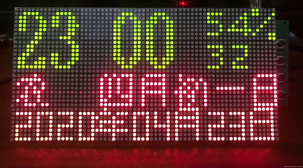
For example, if you look at the screens that show flights at airports and how the letters on them constantly move from left to right, this will be an LED matrix.
Likewise, they are quite common in elevators and in those establishments where you want to show information quickly to the user.
Thus, if you want to know how to manage and display information with LED matrices, you just have to continue reading. Thus:
<center>!Let's get started!</center>

<center><h2>What is an LED matrix?</h2></center>
<center>
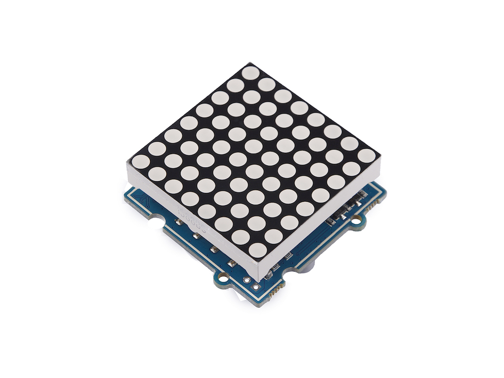
<br>[Shoutout to Seeed Studio Wiki](https://wiki.seeedstudio.com/Grove-Red_LED_Matrix_w_Driver/)</center>
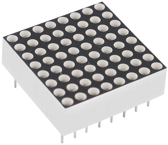
In itself, an LED matrix is a set of LEDs, which are organized in the form of rows and columns. If we look at the following images:
<center>
<br>[Shoutout to buy led card](https://buyledcard.com/what-are-the-different-types-of-led-display-control-systems/)</center>
<center>
<br>[Shoutout to SunFounder's Documentations!](https://docs.sunfounder.com/projects/euler-kit/en/latest/component/component_788bs.html)</center>
<center>
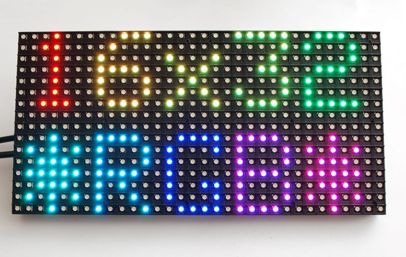
<br>[Shoutout to Adafruit Learning System](https://learn.adafruit.com/32x16-32x32-rgb-led-matrix/overview)</center>
Here, we can notice that there is a wide variety of LED matrices. However, the most popular are usually the 8x8 ones (8 rows and 8 columns, which are 64 LEDs in total), the 5x7 ones (5 rows, 7 columns, 35 Leds) and 8x10.
Now, these matrices can have different configurations, specifically 2, which will determine how the columns and rows should be provided. These two types are:
* Common cathode LED arrays.
* Common anode LED arrays.
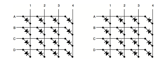
Returning to the 7-segment displays, which are made up of LED diodes, we had these two types of configurations, which determined whether the display had to be powered or grounded for it to work. In the case of LED matrices, the LEDs are organized, so both configurations would look as follows:
<center>
<br>[Shoutout to xerxesbear in the Arduino Forum](https://forum.arduino.cc/t/for-one-colored-led-matrix-common-anode-common-cathode/394400)</center>
Here, if we look at each row, listing by letters and each column by numbers, we can see that in the common cathode LED matrices, all the rows share something in common: That they are connected to the cathodes of the LEDs, while the columns are connected to the anodes.
For common anode arrays it is just the opposite: The rows will be connected to the anodes while the columns will be connected to the cathodes.
So, if we wanted to turn on a particular LED of a common cathode LED array, say the one belonging to row A and column 1, we will have to insert the power to column 1 and place row A to ground, causing this to be illuminate If we have one with a common anode, the power is connected to row A and column 1 is connected to ground.
The same procedure applies if we wanted to turn on all the LEDs in column 1. For this, the power supply (Vcc) is connected to column 1 and rows A, B, C and D are grounded.
Now, how do these illuminated LEDs resemble the figures that we usually see moving around airports?
One thing we must keep in mind is that we cannot illuminate all the columns at the same time to create the figures we want. If we did this we would run into inconveniences such as the fact that if we place a row and a grounded column to create the first part of the figure, when we want to use another row it is most likely that other rows that we do not want will be activated.
To overcome this problem, we just have to resort to a tactic that we used in the previous article: Multiplexing.
When we wanted to illuminate two different displays, we used multiplexing to keep the first display on for a very short time before turning it off and turning on the next display. Then we kept this display on for the same amount of time and returned to the first display, doing this so quickly that it was imperceptible to the human eye.
This is precisely what we will do with LED matrices, where we will use what is known as displacement or "sweep".
In the sweep, we will first place a column on low or high (Depending on whether it is a common anode or cathode) for a moment of time, then turning it off and moving on to the next column, where the same process is repeated. This will be done until reaching the last column, where the sequence will restart and return to the first column.
<center>
<br>[Shoutout to Electgpl Electronica](http://electgpl.blogspot.com/2013/11/matriz-8x8-mensaje-con-desplazamiento.html)</center>
Once we know this, we are ready to create programs with LED arrays. First, let's look at the connections.

<center><h2>Connections</h2></center>
<center>
</center>
When we work with LED matrices on PIC microcontrollers, we can do it in two ways:
* Using two ports of our microcontroller, one for the columns (Where we will do the scanning), and another for the rows, where we will enter the sequences.
* Using only three pins of a port and an additional integrated, a MAX7219, which is an 8-digit driver that will allow us to control the columns and rows of the LED.
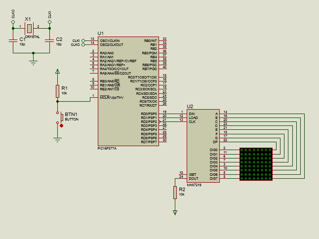
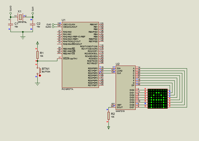
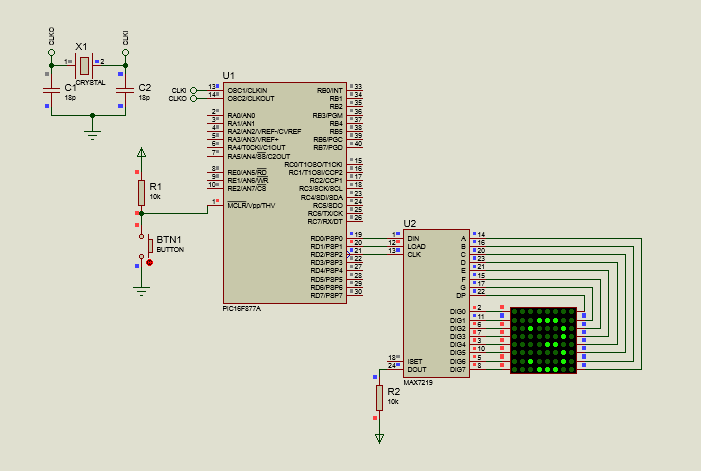
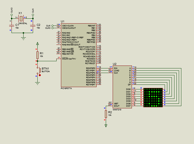
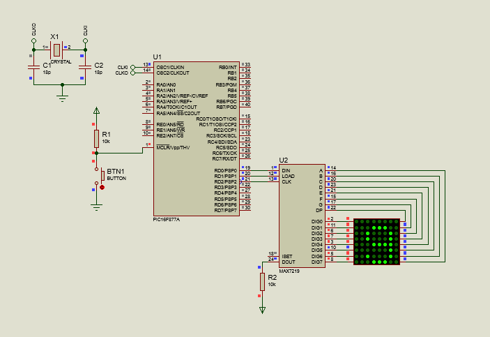
In current times, using the MAX7219 is the simplest option because in addition to using fewer bits, it allows us to use libraries when programming, which make the process of placing characters in the matrix much simpler. Thus, looking at the connection with the MAX7219:
<center>

</center>
Here, we can notice that from port D we will only use three pins, D0, D1 and D2 that will go to the DIN (Data), Load and CLK pins, while DOUT is placed in a pullup resistor with the power supply, this to Control the current flow to the LEDs.
Pins A to DP are connected to the columns, while DIG0 to DIG7 are connected to the columns, making the MAX7219 perform the sweep effect in the same way as we explained previously.
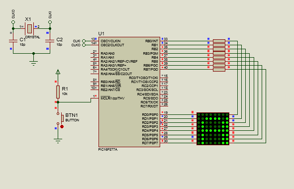
Although we will mostly use circuits with MAX7219, we will also create some with conventional connections to better understand the sweep. Thus, observing:
<center>
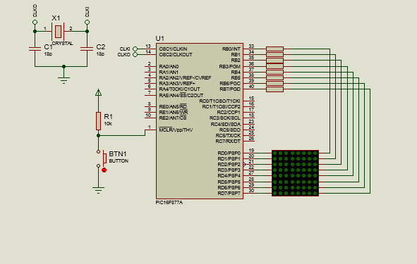
</center>
We can notice that 150Ω resistors will be placed on the columns, which will be the ones to which the power is connected, since the LED matrix is made up of green LEDs, which have a threshold voltage of 2.2V and a current of 20mA, so when calculating, following Ohm's law:
```
Res = Vcc - Vled
------------
Iled
= 5 - 2.20
----------
20x10^-3
= 140Ω
```
So the closest commercial resistance value (150Ω) is used.
Now, looking at the programming for both types of connections:

<center><h2>Setting the code</h2></center>
<center>
</center>
First, taking into account the connection between the PIC and the direct LED matrix, we look at the following code:
```
#include <16f877a.h>
#fuses HS, NOWDT, NOPROTECT, NOPUT, NOLVP, BROWNOUT
#use delay(clock=20M)
#use fast_io(B)
#use fast_io(D)
const int letter_a[8] = {0x00, 0xFC, 0x12, 0x12, 0x12, 0xFC, 0x00, 0x00};
const int offset[8] = {11111110,11111101,11111011,11110111,11101111,11011111,10111111,01111111};
void main()
{
set_tris_d(0x00);
set_tris_b(0x00);
while(TRUE)
{
for(int i = 0; i < 8; i++)
{
output_d(displacement[i]);
output_b(letter_a[i]);
delay_ms(1);
}
}
}
```
Here, we can notice that after using fast_io() for B and D, in order to allow us to configure the pins of these ports as outputs or inputs, we create the relevant arrays.
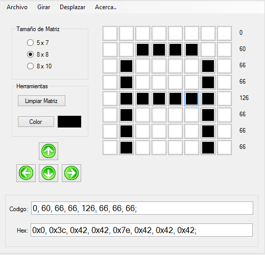
How do we create the arrangement for the letter a? For this, we will use a program that will allow us to create the character and select the type of matrix that is used.
In the matrix size tab we select 8x8, since we will use a matrix with 8 columns and 8 rows, and in the tab where we see the boxes, we click the ones required to create the letter A:
<center>
</center>
We can see that below the figure, there are the code and Hex sections, which have the code to create an array of hexadecimal or decimal elements, depending on our preference. However, if we copy this way, when we look at the value on our screen, we will see it as follows:
<center>
</center>
In order to be able to see the figure in the correct orientation on our LED matrix, we must rotate it counterclockwise. To do this, we go to the rotate tab and click where it says Rotate -90 degrees (This or simply use CTRL+X). This way, we can copy the code for the arrangement and paste it.
If we translated the hexadecimal or decimal code into binary, we would see the following:
<center>
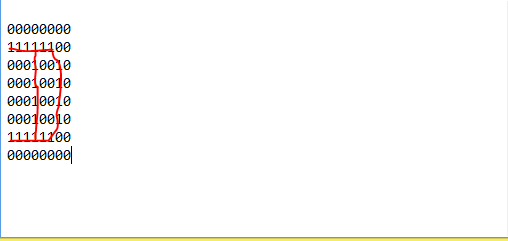
</center>
Which is a letter A.
Then, we create an array, which we call displacement, of 8 elements, which will represent the value that will be assigned to the rows for the sweep or displacement to be carried out, where depending on the row that is intended to be turned on, it will be placed in 0.
Then, after determining in the void main all the pins of port B and D as output (hence the 0x00), within the while(True), the first thing we will do is create a for loop, which will have a counter that will increase until it reaches 8, causing in each iteration, all the outputs of port d (rows) are placed according to the position of the element of the displacement array in the counter index, and the value of the letter array in the same position for the column.
Thus, when executed, we would see the following:
<center>
</center>
> Note: The right column lights up due to compatibility errors with the library in the simulation, which is why it is more reliable to use the MAX7219, where we will not have problems. If you make this circuit physically, A will be shown correctly.
Now, if we wanted to do the same with the MAX7219, this would be much simpler, looking at the following program:
```
#include <16f877a.h>
#fuses HS, NOWDT, NOPROTECT, NOPUT, NOLVP, BROWNOUT
#use delay(clock=20M)
#use standard_io(D)
#define DATA PIN_D0
#define LOAD PIN_D1
#define CLK PIN_D2
#include <MAX7219.c>
void main()
{
display_init(0);
seg_putc("1");
while(TRUE)
{
display_char('A');
}
}
```
Here, we can see that the library called MAX7219.c is used, which allows us to easily control this driver and display a character on the screen without the complexity of executing the displacement in the matrix.
We only have to take into account the following instructions.
display_init(); Where we use 0 as a parameter if the decoding is for a common cathode matrix and 1 if it is for a common anode one.
seg_putc("1"); This is used to determine the array into which the message is to be inserted. In this case it is only one, so "1" is used
display_char(); Here, we place the character to be displayed in the array.
However, for this library to work correctly, we must assign the name DATA, LOAD and CLK to the pins that we want to use on the microcontroller. Otherwise, we would get errors when controlling.
Thus, we define pins D0, D1 and D2 as the required pins, and then include the library. Thus, we start the display and place it in encoding mode 0, when working with a common cathode matrix.
Then, with seg_putc("1") we select the only and first array we have, so that at the end, within the while(), we show the letter A with display_char.
Simple and easy. Now, seeing this in the simulation:
<center>
</center>
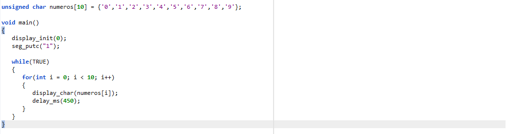
Now, if we wanted to display, for example, the numbers from 0 to 9, we simply create an array with the character values, as we can see in the following code:
```
#include <16f877a.h>
#fuses HS, NOWDT, NOPROTECT, NOPUT, NOLVP, BROWNOUT
#use delay(clock=20M)
#use standard_io(D)
#define DATA PIN_D0
#define LOAD PIN_D1
#define CLK PIN_D2
#include <MAX7219.c>
unsigned char numbers[10] = {'0','1','2','3','4','5','6','7','8','9'};
void main()
{
display_init(0);
seg_putc("1");
while(TRUE)
{
for(int i = 0; i < 10; i++)
{
display_char(numbers[i]);
delay_ms(450);
}
}
}
```
We note that the array created will be of type unsigned char since the values will be of type character, and within this array, we place the values corresponding to 0,1,2,3,4,5,6,7,8 and 9.
Later, within the void main(), we start the display and select the matrix in the same way.
For the while loop, we will now create a for loop that will go through all the positions of the array, which is why it will stop at the number before 10. Within this for, we will display in the array the value of the array at position i, and then wait 450ms so that we can see the character without problems.
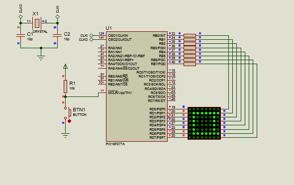
And when simulated, we would have the following:
<center>
</center>
<center>
</center>
<center>
</center>
If we want to do the same without using the MAX7219, we just have to repeat the process of the first program, where we create more than one array to include more letters, in addition to using more for loops to cycle through these. In this:
```
#include <16f877a.h>
#fuses HS, NOWDT, NOPROTECT, NOPUT, NOLVP, BROWNOUT
#use delay(clock=20M)
#use fast_io(B)
#use fast_io(D)
const int letter_a[8] = {0x00, 0xFC, 0x12, 0x12, 0x12, 0xFC, 0x00, 0x00};
const int letter_b[8] = {0x00, 0xFE, 0x92, 0x92, 0x92, 0x6C, 0x00, 0x00};
const int letter_c[8] = {0x00, 0x38, 0x44, 0x82, 0x82, 0x82, 0x00, 0x00};
const int offset[8] = {11111110,11111101,11111011,11110111,11101111,11011111,10111111,01111111};
int i, j, k;
void main()
{
set_tris_d(0x00);
set_tris_b(0x00);
while(TRUE)
{
for(int cont1 = 0; cont1 < 60; cont1++)
{
for(i = 0; i < 8; i++)
{
output_d(displacement[i]);
output_b(letter_a[i]);
delay_ms(1);
}
}
for(int cont2 = 0; cont2 < 60; cont2++)
{
for(j = 0; j < 8; j++)
{
output_d(displacement[j]);
output_b(letter_b[j]);
delay_ms(1);
}
}
for(int cont3 = 0; cont3 < 60; cont3++)
{
for(k = 0; k < 8; k++)
{
output_d(displacement[k]);
output_b(letter_c[k]);
delay_ms(1);
}
}
}
}
```
Here, we can notice that in addition to the letter_a array, the letter_b and letter_c arrays are created, to create a sequence where the letters a through c are displayed, which is why more than one counter variable is also created (i, j and k).
Now, within the while, we start by creating a for loop with a variable called cont2, which will be a counter to create a delay effect, allowing us to see the character for about 60ms before moving on to the next one.
Thus, we make the counter run while it is less than 60 and increase, and then create another nested for loop which will be the one that cycles through the arrangements of the letters and the displacement.
Within this, we apply the same, the output b, dedicated to the rows, will be placed in the index element i in the array letter_a, while in the columns the displacement will be executed through port d.
Then, what we would do is repeat these lines of code, changing the counters that would be used, showing in the other cases the elements in the indexes arranged for the letter_b and letter_c arrays.
Thus, physically it would allow us to see the sequence of letters. However, in the simulation we will have errors and it would not be displayed correctly, which is why when simulating it is better to use the MAX7219.

Managing LED matrices is also very simple, as long as you understand the position of the LEDs and how they are distributed in rows and columns.
After this article, you will be able to show character in these matrices without problem. However, I know that this is still far from the words that move from left to right, which we see every day.
Don't worry, because in the next post I will talk about this. Meanwhile, I hope this has been helpful and allows you to practice to gain mastery of these technologies.
Thus:

<center>Thank you very much for your support and good luck!</center>


<center><h1>Trabajando con Matrices LED</h1></center>
<center>

<br>[Shoutout to Embedded Lab](https://embedded-lab.com/blog/lab-12-basics-of-led-dot-matrix-display/)</center>

<center><h3>En este artículo encontrarás:</h3></center>
* <b>Introducción</b>
* <b>¿Qué es una matriz LED?</b>
* <b>Conexiones</b>
* <b>Estableciendo el Código</b>

Un saludo a todos. Mil disculpas por haber faltado con el artículo del Domingo. Estaba resolviendo algunos inconvenientes, pero ya todo ha sido solucionado.
De esta forma, damos pie a otra edición de Microcontroladores, donde seguiremos observando elementos para mostrar información, que en este caso serán las matrices LED.
Puede que este término te suene peculiar. Sin embargo, las probabilidades de que hayas visto una de estas es realmente alta.
Por ejemplo, si te fijas en las pantallas que muestran los vuelos en los aeropuertos y como las letras en estos se mueven constantemente de izquierda a derecha, esto será una matriz LED.
De igual forma, son bastante comunes en ascensores y en aquellos establecimientos donde se quiera mostrar información de manera rápida al usuario.
Así, si quieres saber como manejar y mostrar información con matrices LED, solo tienes que seguir leyendo. De esta forma:
<center>!Comencemos!</center>

<center><h2>¿Qué es una matriz LED?</h2></center>
<center>

<br>[Shoutout to Seeed Studio Wiki](https://wiki.seeedstudio.com/Grove-Red_LED_Matrix_w_Driver/)</center>
En si, una matriz led es un conjunto de LEDs, los cuales se encuentran organizados en forma de filas y columnas. Si observamos las siguientes imágenes:
<center>

<br>[Shoutout to buy led card](https://buyledcard.com/what-are-the-different-types-of-led-display-control-systems/)</center>
<center>

<br>[Shoutout to SunFounder's Documentations!](https://docs.sunfounder.com/projects/euler-kit/en/latest/component/component_788bs.html)</center>
<center>

<br>[Shoutout to Adafruit Learning System](https://learn.adafruit.com/32x16-32x32-rgb-led-matrix/overview)</center>
Aquí, podemos notar que existe una gran variedad de matrices LED. Sin embargo, las más populares suelen ser las de 8x8 (8 filas y 8 columnas, que en total son 64 leds), los de 5x7(5 filas, 7 columnas, 35 Leds) y 8x10.
Ahora bien, estas matrices pueden tener distintas configuraciones, específicamente 2, que determinarán como las columnas y las filas deben de ser provistas. Estos dos tipos son:
* Matrices LED de cátodo común.
* Matrices LED de ánodo común.
Volviendo a los displays de 7 segmentos, que están formados por diodos LED, teníamos estos dos tipos de configuraciones, los cuales determinaban si el display debía de ser alimentado o colocado a tierra para que funcionase. En el caso de las matrices LEDs, los LEDs se encuentran organizados, por lo que ambas configuraciones se verían de la siguiente manera:
<center>

<br>[Shoutout to xerxesbear in the Arduino Forum](https://forum.arduino.cc/t/for-one-colored-led-matrix-common-anode-common-cathode/394400)</center>
Aquí, si observamos cada fila, enumerando por letras y cada columna por números, podemos ver que en las matrices LED de cátodo común, todas las filas comparten algo en común: Que estas se encuentran conectadas a los cátodos de los LED, mientras que las columnas están conectadas a los ánodos.
Para las matrices de ánodo común es todo lo contrario: Las filas estarán conectadas a los ánodos mientras que las columnas se conectarán a los cátodos.
Así, si quisieramos encender un LED en particular de una matriz LED de cátodo común, digamos el perteneciente a la fila A y la columna 1, tendremos que insertar la alimentación a la columna 1 y colocar la fila A a tierra, haciendo que este se ilumine. Si tenemos una de ánodo común, a la fila A se conecta la alimentación y la columna 1 se conecta a la tierra.
El mismo procedimiento aplica si quisieramos encender todos los leds de la columna 1. Para esto, se conecta la alimentación (Vcc) a la columna 1 y se ponen a tierra las filas A,B,C y D.
Ahora bien, ¿Cómo se asemejan estos leds iluminados a las figuras que solemos ver desplazándose en los aeropuertos?
Una cosa que debemos de tener en cuenta es que no podemos iluminar al mismo tiempo todas las columnas para crear las figuras que queremos. Si hicieramos esto nos encontraríamos con inconvenientes como el hecho de que si colocamos una fila y una columna a tierra para crear la primera parte de la figura, cuando queramos usar otra fila lo más probable es que se activen otras filas que no queremos.
Para superar este inconveniente, solo tenemos que recorrer a una táctica que usamos en el artículo anterior: La multiplexación.
Cuando queríamos iluminar dos displays distintos, usabamos la multiplexación para mantener el primer display encendido por un tiempo muy corto antes de apagarlo y encender el siguiente display. Luego manteníamos este display encendido por el mismo tiempo y volvíamos al primer display, haciendo esto de una forma tan rápida que era imperceptible para el ojo humano.
Esto es precisamente lo que haremos con las matrices LED, donde utilizaremos lo que se conoce como desplazamiento o "barrido".
En el barrido, primero colocaremos una columna en bajo o en alto (Dependiendo de si es de ánodo o cátodo común) por un instante de tiempo, luego apagando esta y pasando a la siguiente columna, donde se repite el mismo proceso. Esto se hará hasta llegar a la última columna, donde se reiniciará la secuencia y se volverá a la primera columna.
<center>

<br>[Shoutout to Electgpl Electrónica](http://electgpl.blogspot.com/2013/11/matriz-8x8-mensaje-con-desplazamiento.html)</center>
Una vez que sabemos esto, estamos preparados para crear programas con matrices LED. Primero, veamos las conexiones.

<center><h2>Conexiones</h2></center>
<center>

</center>
Cuando trabajamos con matrices LED en microcontroladores PIC, podemos hacerlo de dos formas:
* Usando dos puertos de nuestro microcontrolador, uno para las columnas (Donde haremos el barrido), y otro para las filas, donde introduciremos las secuencias.
* Usando solo tres pines de un puerto y un integrado adicional, un MAX7219, que es un driver de 8 dígitos que nos permitirá controlar las columnas y filas del LED.
En tiempos actuales, el uso del MAX7219 es la opción más sencilla debido a que además de usar menos bits, nos permite usar librerías al programar, que hacen el proceso de colocar caracteres en la matriz mucho más sencillo. Así, observando la conexión con el MAX7219:
<center>

</center>
Aquí, podemos notar que del puerto D solo usaremos tres pines, el D0, el D1 y el D2 que irán a los pines DIN (Data), Load y CLK, mientras que DOUT se coloca en una resistencia pullup con la alimentación, esto para controlar el flujo de corriente hacia los leds.
Los pines del A al DP se conecta a las columnas, mientras que de DIG0 a DIG7 se conectan a las columnas, haciendo que el MAX7219 realice el efecto de barrido de la misma forma que explicamos previamente.
Aunque usaremos en su mayoría circuitos con MAX7219, también crearemos algunos con conexiones convencionales para entender mejor el barrido. Así, observando:
<center>

</center>
Podemos notar que a las columnas, que será a las que se conecta la alimentación, se colocarán resistores de 150Ω, esto ya que la matriz LED está formada por leds verdes, que tienen un voltaje de umbral de 2.2V y una corriente de 20mA, con lo que al calcular, siguiendo la ley de Ohm:
```
Res = Vcc - Vled
------------
Iled
= 5 - 2.20
----------
20x10^-3
= 140Ω
```
Con lo que se usa el valor de resistencia comercial más cercano (150Ω).
Ahora, viendo la programación para ambos tipos de conexiones:

<center><h2>Estableciendo el código</h2></center>
<center>

</center>
Primero, tomando en cuenta la conexión entre el PIC y la matriz LED directa, observamos el siguiente código:
```
#include <16f877a.h>
#fuses HS, NOWDT, NOPROTECT, NOPUT, NOLVP, BROWNOUT
#use delay(clock=20M)
#use fast_io(B)
#use fast_io(D)
const int letra_a[8] = {0x00, 0xFC, 0x12, 0x12, 0x12, 0xFC, 0x00, 0x00};
const int desplazamiento[8] = {11111110,11111101,11111011,11110111,11101111,11011111,10111111,01111111};
void main()
{
set_tris_d(0x00);
set_tris_b(0x00);
while(TRUE)
{
for(int i = 0; i < 8; i++)
{
output_d(desplazamiento[i]);
output_b(letra_a[i]);
delay_ms(1);
}
}
}
```
Aquí, podemos notar que después de usar los fast_io() para B y D, en orden de permitirnos configurar los pines de estos puertos como salidas o entradas, creamos los arreglos pertinentes.
¿Cómo creamos el arreglo para la letra a? Para esto, usaremos un programa que nos permitirá crear el caracter y seleccionar el tipo de matriz que se usa.
En la pestaña de tamaño de matriz seleccionamos 8x8, ya que usaremos una matriz de 8 columnas y 8 filas, y en la pestaña donde observamos las casillas, clickeamos las requeridas para crear la letra A:
<center>

</center>
Podemos observar que debajo de la figura, se tiene las secciones de código y Hex, que tienen el código para crear un arreglo de elementos hexadecimales o decimales, según sea nuestra preferencia. Sin embargo, si copiamos de esta manera, cuando observemos el valor en nuestra pantalla, lo veremos de la siguiente manera:
<center>

</center>
En orden de poder ver la figura con la orientación correcta en nuestra matriz LED, debemos de girar esta en un sentido antihorario. Para esto, nos dirigimos a la pestaña de girar y clickeamos donde dice Girar -90 grados (Esto o simplemente usar CTRL+X). De esta forma, podemos copiar el código para el arreglo y lo pegamos.
Si traducieramos el código hexadecimal o decimal a binario, veríamos lo siguiente:
<center>

</center>
Lo cual es una letra A.
Luego, creamos un arreglo, al que llamamos desplazamiento, de 8 elementos, el cual representará el valor que se le asignará a las filas para que se realice el barrido o desplazamiento, donde dependiendo de la fila que se pretenda encender, se colocará esta en 0.
Luego, después de determinar en el void main a todos los pines del puerto B y D como salida (Por esto el 0x00), dentro del while(True), lo primero que haremos será crear un ciclo for, el cual tendrá un contador que aumentará hasta llegar a 8, haciendo que en cada iteración, se pongan todas las salidas del puerto d (filas) según la posición que tenga el elemento del arreglo de desplazamiento en el índice del contador, y el valor del arreglo letra en la misma posición para la columna.
Así, al ejecutar, veríamos lo siguiente:
<center>

</center>
> Nota: La columna de la derecha se ilumina por errores de compatibilidad con la librería en la simulación, razón por la que es mas confiable usar el MAX7219, donde no tendremos problemas. Si realizas este circuito en físico, se mostrará la A de manera correcta.
Ahora, si quisieramos hacer lo mismo con el MAX7219, esto sería mucho más sencillo, observando el programa consecuente:
```
#include <16f877a.h>
#fuses HS, NOWDT, NOPROTECT, NOPUT, NOLVP, BROWNOUT
#use delay(clock=20M)
#use standard_io(D)
#define DATA PIN_D0
#define LOAD PIN_D1
#define CLK PIN_D2
#include <MAX7219.c>
void main()
{
display_init(0);
seg_putc("1");
while(TRUE)
{
display_char('A');
}
}
```
Aquí, podemos ver que se usa la librería llamada MAX7219.c, la cual nos permite controlar de manera sencilla este driver y mostrar un caracter en la pantalla sin la complejidad de ejecutar el desplazamiento en la matriz.
Solamente debemos de tener en cuenta las siguientes instrucciones.
display_init(); Donde usamos como parámetro 0 si la decodificación es para una matriz de cátodo común y 1 si es para una de ánodo común.
seg_putc("1"); Este se usa para determinar la matriz en la cual se va a insertar el mensaje. En este caso es una sola, por lo que se usa "1"
display_char(); Aquí, colocamos el caracter para que se muestre en la matriz.
Sin embargo, para que esta librería funcione correctamente, debemos de asignar el nombre de DATA, LOAD y CLK a los pines que deseamos usar del microcontrolador. De otra forma, obtendríamos errores al controlar.
Así, definimos a los pines D0,D1 y D2 como los pines requeridos, para luego incluir la librería. Así, iniciamos el display y lo colocamos en modo de codificación 0, al trabajar con una matriz de cátodo común.
Luego, con seg_putc("1") seleccionamos la única y primera matriz que tenemos, para que al final, dentro del while(), mostremos la letra A con display_char.
Simple y sencillo. Ahora, al ver esto en la simulación:
<center>

</center>
Ahora, si quisieramos mostrar, por ejemplo los números de 0 al 9, simplemente creamos un arreglo con los valores de caracteres, como podemos observar en el siguiente código:
```
#include <16f877a.h>
#fuses HS, NOWDT, NOPROTECT, NOPUT, NOLVP, BROWNOUT
#use delay(clock=20M)
#use standard_io(D)
#define DATA PIN_D0
#define LOAD PIN_D1
#define CLK PIN_D2
#include <MAX7219.c>
unsigned char numeros[10] = {'0','1','2','3','4','5','6','7','8','9'};
void main()
{
display_init(0);
seg_putc("1");
while(TRUE)
{
for(int i = 0; i < 10; i++)
{
display_char(numeros[i]);
delay_ms(450);
}
}
}
```
Notamos que el arreglo creado será de tipo unsigned char ya que los valores serán de tipo caracter, y dentro de este arreglo, colocamos los valores correspondientes a 0,1,2,3,4,5,6,7,8 y 9.
Posteriormente, dentro del void main(), iniciamos el display y seleccionamos la matriz de la misma forma.
Para el ciclo while, ahora crearemos un ciclo for que recorrerá todas las posiciones del arreglo, razón por la que se detendrá en el número anterior al 10. Dentro de este for, mostraremos en la matriz el valor del arreglo en la posición de i, para luego esperar 450ms en orden de que podamos ver el caracter sin problemas.
Y al simular, tendríamos lo siguiente:
<center>

</center>
<center>

</center>
<center>

</center>
Si queremos realizar lo mismo sin el uso del MAX7219, solo tenemos que repetir el proceso del primer programa, donde creamos más de un arreglo para incluir más letras, además de usar más ciclos for para recorrer estos. En este:
```
#include <16f877a.h>
#fuses HS, NOWDT, NOPROTECT, NOPUT, NOLVP, BROWNOUT
#use delay(clock=20M)
#use fast_io(B)
#use fast_io(D)
const int letra_a[8] = {0x00, 0xFC, 0x12, 0x12, 0x12, 0xFC, 0x00, 0x00};
const int letra_b[8] = {0x00, 0xFE, 0x92, 0x92, 0x92, 0x6C, 0x00, 0x00};
const int letra_c[8] = {0x00, 0x38, 0x44, 0x82, 0x82, 0x82, 0x00, 0x00};
const int desplazamiento[8] = {11111110,11111101,11111011,11110111,11101111,11011111,10111111,01111111};
int i, j, k;
void main()
{
set_tris_d(0x00);
set_tris_b(0x00);
while(TRUE)
{
for(int cont1 = 0; cont1 < 60; cont1++)
{
for(i = 0; i < 8; i++)
{
output_d(desplazamiento[i]);
output_b(letra_a[i]);
delay_ms(1);
}
}
for(int cont2 = 0; cont2 < 60; cont2++)
{
for(j = 0; j < 8; j++)
{
output_d(desplazamiento[j]);
output_b(letra_b[j]);
delay_ms(1);
}
}
for(int cont3 = 0; cont3 < 60; cont3++)
{
for(k = 0; k < 8; k++)
{
output_d(desplazamiento[k]);
output_b(letra_c[k]);
delay_ms(1);
}
}
}
}
```
Aquí, podemos notar que adicionalmente del arreglo letra_a, se crean los arreglos letra_b y letra_c, para crear una secuencia donde se muestren las letras de la a hasta la c, razón por la cual también se crea más de una variable de contador (i,j y k).
Ahora, dentro del while, empezamos creando un ciclo for con una variable llamada cont2, el cual será un contador para crear un efecto de retardo, permitiendo que podamos ver el caracter por unos 60ms antes de pasar al siguiente.
Así, hacemos que el contador se ejecute mientras sea menor a 60 y que aumente, para luego crear otro ciclo for anidado el cual si será el que recorra los arreglos de las letras y el de desplazamiento.
Dentro de este, aplicamos lo mismo, la salida b, dedicada a las filas se colocará en el elemento de índice i en el arreglo letra_a, mientras que en las columnas se ejecutará el desplazamiento por el puerto d.
Luego, lo que haríamos sería repetir estas lineas de código, cambiando los contadores que se usarían, mostrando en los otros casos los elementos en los índices dispuestos para los arreglos letra_b y letra_c.
Así, de forma física nos permitiría ver la secuencia de letras. Sin embargo en la simulación tendremos errores y no se mostraría correctamente, razón por la que al simular es mejor usar el MAX7219.

El manejo de matrices LED también es algo muy sencillo, siempre y cuando se entienda la posición de los LEDS y como estos se distribuyen en filas y columnas.
Después de este artículo, podrás mostrar caracter en estas matrices sin problema. Sin embargo, sé que esto todavía dista de las palabras que se desplazan de izquierda a derecha, las cuales vemos cotidianamente.
No te preocupas, pues en el siguiente post hablaré de esto. Mientras, espero que este haya sido de ayuda y que les permita practicar para obtener dominio de estas tecnologías.
De esta forma:

<center>¡Muchas gracias por tu apoyo y buena suerte!</center>


</div>